

.webp "Fiber Mux & OADM")


")
")


WHAT IS ARRAYED WAVEGUIDE GRATING
Arrayed Waveguide Grating (AWG) is commonly used as optical multiplexer/demultiplexer (MUX/DeMUX) in Wavelength Division Multiplexing (WDM) systems. The AWG devices are capable of multiplexing a large number of wavelengths into a single optical fiber, thereby increasing the transmission capacity of optical networks considerably.
AWGs are based on a fundamental principle of optics that light waves of different wavelengths interfere linearly with each other. This means that, if each channel in an optical communication network makes use of light of a slightly different wavelength, then the light from a large number of these channels can be carried by a single optical fiber with negligible crosstalk between the channels. The AWGs are used to multiplex channels of several wavelengths onto a single optical fiber at the transmission end and are also used as demultiplexers to retrieve individual channels of different wavelengths at the receiving end of an optical communication network.

Based on the substrate, an AWG consists of an array of waveguides (also called phased array) and two couplers (also called the free propagation region – FPR). One of the input waveguides carries an optical signal consisting of multiple wavelengths λ1 – λn into the first (input) coupler, which then distributes the light amongst an array of waveguides.
The light subsequently propagates through the waveguides to the second (output) coupler. The length of these waveguides is chosen so that the optical path length difference between adjacent waveguides, dL equals an integer multiple of the central wavelength λc of the demultiplexer. For this wavelength the fields in the individual arrayed waveguides will arrive at the input of the output coupler with equal phase, and the field distribution at the output of the input coupler will be reproduced at the input of the output coupler. Linearly increasing length of the array waveguides will cause interference and diffraction when light mixes in the output coupler. As a result, each wavelength is focused into only one of the N output waveguides (also called output channels).
AWG BASIC PRINCIPLE
1. Phase accumulation in each waveguide: Φ = 2 π * n(T)*L / λ
2. Differential waveguide length generate different phase tilt for different wavelength.
3. Single waveguide effective index and the design of waveguide length difference are responsible for wavelength multiplexing function.
AWG FABRICATION
The AWG is a planar waveguide structure usually obtained on silicon wafer substrate with a SiO2 lower cladding oxide obtained using thermal oxidation of Si substrate. Chemical vapor deposition (CVD) process creates GeSiO2 active layer with refractive index higher than the refract ive index of the cladding layer. Optical lithography and dry etching define then AWG waveguide structure. The growth of the upper cladding (CVD process) with refractive index matching with lower cladding is the last technological step.
Because the fabrication of the AWG is based on standardizes techniques, the integration of the AWG offers many advantages such as compactness, reliability, fabrication stability, an d significantly reduced fabrication and packaging costs.
The inherent advantages of the AWG also include precisely-controlled channel spacing (easily matched to the ITU grid) simple and accurate wavelength stabilization, low and uniform insertion loss, narrow and accurate channel spacing, and large channel numbers.
AWG TYPES
Various AWGs are available on the market. They can be divided into two main groups according to the material used: so-called low-index and high-index AWGs. Low-index AWGs with a typical refractive index contrast of 0.75% have the advantage of their compatibility with optical fibers, and hence very low coupling losses between output waveguides and optical fibers. The disadvantage of such AWGs is their size, which corresponds with the waveguide curvature that may not lie below a critical value. As a result, increasing the channel counts and narrowing the channel spacing leads to a rapid increase in the AWG size and this, in turn; causes the deterioration in optical performance like higher insertion loss and, in particular, higher channel crosstalk. In contrast to this, high-index AWGs feature a much smaller size but also much higher coupling losses.
As the number of waveguides used to carry the information in DWDM systems is generally a power of 2, the AWGs are designed to separate two different wavelengths, or 4, 16, 32, 64 etc. In addition to this, 40- and 80-channel AWGs are also available. Systems being deployed at present usually have no more that 40 wavelengths, but technological advancements will continue to make higher numbers of wavelengths possible.
The wavelengths being used to transmit the information are usually around the 1550 nm region, the wavelength region in which optical fiber performs best (it has very low loss and low attenuation). Each wavelength is separated from the previous one by a multiple of 0.8 nm (also referred to as 100 GHz spacing, which is the frequency separation). However, they can be also separated by 1.6 nm (i.e. 200 GHz) or another spacing as long as it is a multiple of 0.8 nm. These channel spacings refer to WDM systems. On the other hand, increasing capacity demands mean the present aim is to squeeze even more wavelengths into an even tighter space, which may result in as little as half the regular spacing, i.e. 0.4 nm (50 GHz) or even a quarter, 0.2 nm (25 GHz). Such narrow channel spacings are being used in DWDM systems. However, the recent rapid growth in network capacity has meant that even higher capacity transmission is required in DWDM systems. To meet the growing capacity demands, it is necessary to continue increasing the channel counts of these AWGs as far as possible, i.e. decreasing their channel spacing going down to 10 GHz or less. Such AWGs play a key role in the very high density WDM applications.
The optical signals transmitted can have different shapes. The most common is the Gaussian passband (or Gaussian shape) which features very low insertion loss. In contrast to this, the flat-top passband suffers far higher insertion losses but features much better detection conditions. Somewhere between these two shapes lies so-called semi-flat passband, this is also often used in DWDM systems.
A special part of the AWG family creates so-called "cyclic" or "colorless" AWG with an usual 100 GHz or 50 GHz channel spacing and 8 (or 16) output channels. Here applying a special design such AWG will repeat its orders and can work in any predefined channel band. In other words, the same colorless AWG can work on channels 1 to 8 or 9 to 16 or 17 to 24, and so on.
THERMAL CONTROL OF AWG
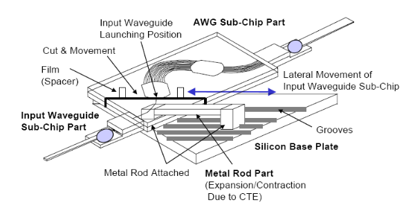
In order to use AWG devices in practical optical communications' applications, precise wavelength control and long-term wavelength stability are needed. Of course, if the temperature of an AWG fluctuates, the channel wavelength will change according to the thermal coefficient of the material used. By making use of the thermo-optic effect, a temperature controller can be build into the AWG to control and tune the device to the ITU grid or any other desired wavelength. Recently companies have demonstrated the use of Athermal AWG devices. The principle involves using a special silicon resin in part of the lightwave circuit that has a different temperature coefficient than quartz glass. This design cuts the temperature dependence of the wavelengths of transmitted light to less then one tenth of its original value, which makes using a temperature-control device unnecessary.
Effect of Temperature on AWG
Temperature controlling of Thermal AWG
Thermal AWG is base on stably temperature controlling to chip. Athermal AWG is base on mechanical re-alignment. In standard AWGs the temperature of the AWG chip is stabilized.
AWG APPLICATIONS

The AWG has already been used in point-to-point DWDM systems and is a key component in the construction of flexible and large-capacity DWDM communication systems. AWG offers the advantages of low loss, high port counts, and mass productivity. Further progress on the AWG is expected to contribute greatly to the construction of future photonic communication systems including Optical Add/Drop Multiplexing (OADM) systems and Optical Cross Connect (OXC) systems.
1. Optical Network (DWDM transmission, OXCs, OADMs)
OXC application: a. Mesh network, nodes with connectivity >2; b. Ring interconnect
OADM application: a. Nodes in ring networks; b. Intermediate nodes on linear spans; c. Between larger OXC nodes
2. λ-by-λ management (provisioning/protection/restoration)
OADM drops λ’s from incoming DWDM signal to local receivers, adds new signals (same λ) from local transmitters
OADM ports : in, out connected to network. Add, drop connected to local transmitters, receivers

In this section, we describe at what points in an optical network AWGs can be used. Generally AWG devices serve as multiplexers, demultiplexers, filters, and add-drop devices in optical WDM and DWDM applications:
1. At the transmission point of a DWDM long- haul network, they can be used to multiplex the numerous WDM channels into one fibre before the optical fibre amplifiers.
2. They can also be used as demultiplexers at receiver end of such systems.
3. AWGs can be implemented in the OADM part of long-haul communication systems.
4. They are finding increasing use in FTTx systems as CWDM MUX/DeMUX.
ULTRA WIDE AWGS FOR DWDM SYSTEMS
The use of WDM systems is increasing rapidly and, in these systems, AWG plays an important role as MUX/DeMUX (i.e. DWDM MUX/DeMUX). The AWGs offer compactness, high stability, excellent optical characteristics, and mass producibility. Until now, AWGs have been developed solely for telecommunication applications, so their wavelength range has been limited to 1.3–1.6 μm.
However, for novel applications such as sensors. AWGs with a shorter wavelength range, including the visible wavelength range. This is because many materials and analyses have specific characteristics at these wavelengths. Until now, only theoretical consideration has been given to AWGs operating in the visible wavelength range.
One of the key advantages of AWGs is their ability to provide the fine wavelength resolution required for optical spectroscopic sensors designed to identify materials and analyses. This arises from the design flexibility of the waveguide layout and enables us to obtain arbitrary spectroscopic characteristics by changing the path length difference between neighboring arrayed waveguides and the focal length of the slab waveguides.
Planar Lightwave Circuit (PLC) technology and design have evolved significantly in the past decade in terms of both performance and yield. New semiconductor techniques applied to integrated optics have dramatically improved wafer quality in parallel, design efforts have led to lowering insertion loss, reducing crosstalk, increasing channel bandwidth, decreasing channel spacing, and managing chromatic dispersion (CD).
With AWGs that match or exceed the performance of thin-film filters, and will enable with the integration of variable optical attenuators and monitoring taps to realize high-performance and low cost modules with added functions for the system. Desirable characteristics of any AWG device include low loss in the passbands, high loss outside the passbands, uniform loss within one channel and channel-to-channel, and polarization independent behavior. While low crosstalk is of paramount importance in demultiplexers where out-of-band signals appear as loss outside the passbands, uniform loss within one channel and channel-to-channel, and polarization independent behavior. While low crosstalk is of paramount importance in demultiplexers where out-of-band signals appear as noise at the receiver, it is of little concern in multiplexers where out-of-band signals simply are not present in the transmitter. For multiplexing, a flat response within the passband is highly desirable in order to account for wavelength drift in the laser source.
COMPARISON OF THERMAL AND ATHERMAL AWGS
1. Both thermal and athermal AWG are widely used as a DWDM and OADM in optical network.
2. AWG application technology is base on well waveguides theory and technology.
3. Thermal key process is stably operation temperature by electrical controlling, Athermal key process is stably mechanical compensation by micro-mechanical re-alignment when environment temperature change.
Bulk Fiber Optic Cables OM3, OM4 Fiber, Tight Buffer, Indoor & Outdoor, LSZH, Figure8, ADSS Fiber Cables |
Fiber Optic Patch Cables 10G Patch Cable, Single Mode, Multimode, Armored, MPO/MTP Turnk Cables, & Pigtails |
Fiber Optic Transceivers SFP, SFP+, XFP, XENPAK, DWDM, CWDM, 40G QSFP+ & CFP Modules |
-consulting for technical supports or relevent product buying guide
Email for [email protected]


No comments have been posted yet.