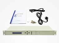
FTTx network construction is becoming a hot spot access network at home and abroad. PON access network technology is recognized as the industry's best solution for FTTx. This technology allows multiple users to share a single fiber, so that it does not need to use any active devices in the optical distribution network (ODN), which means that it does not need to use the OEO conversion. This single point-to-multipoint architecture greatly reduces network installation, management and maintenance costs.
.jpg)
In PON system, uplink signal is 1310nm wavelength, and downlink signal has 1490nm and 1550nm wavelength, respectively, in the opposite direction along the same optical fiber transmission. G.983 ensure the 1310nm upstream signal to remain silent until 1490nm downstream signal round robin and assigned a transmission window, which means 1310nm upstream signal for passive light, because it must establish a communication link between OLT (1490nm downstream signal) and ONU (1310nm uplink signal) to measure 1310 uplink signal. When using uplink signals division multiple access (TDMA) mode to the uplink information of the plurality of optical network units (ONU) is organized into a time-division multiplexing (TDM) information flows are sent to the optical line terminal (OLT). In this structure uplink access must be used the burst mode. The optical signal on the line is the burst optical signal. To correctly detect the burst optical signals, it is necessary to detect the average optical power of the transmitter-activated light emission period, while the ordinary standard optical power meter can only properly test continuous optical signals. So, if you use a traditional optical power meter (recording the average optical power within a sampling period) , it will not be able to get the correct test results. This bings the network installation and maintenance difficulties, therefore we need a new type of optical power meter to meet the test requirements of the PON system power.
From the above we know that an optical power meter used in the PON system testing should meet the following requirements.
1. Simultaneous measurement the light power with three wavelengths of 1310nm, 1490nm, and 1550nm.
2. Can provide the online test of optical power.
3. Burst signal light power can be tested correctly.

Figure 1 - structure of optical path
It requires special optical structure in order to achieve the two functions 1 and 2. Figure 1 is such an optical structure. As shown in the figure, the optical power meter uses a structure with two heads, 10% spectral test line with a bi-directional coupler, direct access uplink signals (1310nm) spectral detectors power detection. Signal line (1490nm and 1550nm) of spectroscopic and then high isolation WDM wavelength separately and then access the the detector power detection. This will be able to simultaneously detect a three-wavelength optical power, and the line maintain a normal communication during the measurement.
The basic idea of burst optical signal power detection is the use of signal conversion, signal shaping, timing synchronization, the delay trigger control and signal sample and hold technique, the high frequency burst mode optical signal into a low frequency can be maintained for the electrical signal pulse level, combined with the detection process, in order to achieve the detection of the PON system, an upstream burst optical signal power. Its specific implementation process is as follows:
The front-end signal processing circuit is designed to focus, i.e. the pre-amplifier and the shaping network portion, it PIN diode light generated current signal is converted into a voltage signal having a certain linear corresponding relationship will directly affect the quality of the voltage signal subsequent circuit detection accuracy and stability.
The quality of the signal conversion impact consists of the following three aspects.
First, the bandwidth, the gain and noise of the amplifier;
Second, PIN junction capacitance of the tube, the junction resistance, dark current and noise;
Third, the power supply ripple and noise, circuit noise.
For this reason, you should choose operational amplifier with high-bandwidth, gain and less noise; PIN tube with high bandwidth, small junction capacitance and noise. In order to reduce the junction capacitance and noise, you should plus PIN with reverse bias voltage. Good signal shaping network can improve the quality of the voltage signal well.
Experiments show that: using the optical path and circuit design structure in this article, the testing requirements of the optical power in the PON system are done perfectly, namely the three wavelength optical power test, the correct test of the online test and 1310nm uplink signal burst optical power. The excellent performance optical power meter used in the PON system testing can be produced, which is convenient to the PON system installation, management and maintenance.
Featured Products
Compatible SFP+ Supply Customize Compatible SFP+ Module to fit your specific requirements | SDH Optical Amplifiers Booster Amplifier, in-line Amplifier, Pre-Amplifier for SDH networks | SDI&HDMI&VGA Fiber Converter SDI, 3G-SDI, HD-SDI, and SDI-HDMI over fiber video converter. |
Email for Technical Tips
-consulting for technical supports or relevent product buying guide
Email for Sales
-consulting for technical supports or relevent product buying guide
Email for Sales


No comments have been posted yet.