1550nm ITU標準波長直接変調光送信機10mw標準
1550nmインテリジェント直接変調光送信機は、主に1550nm光ファイバ伝送システムに使用され、CATVネットワークを構築するための最も重要な機器です。主にテレビ画像信号、デジタルテレビ信号、電話音声信号、データ(または圧縮データ)信号などの付加価値サービスに使用されます。内蔵WDMにより、インターカット光信号とメイン光信号を多重化して出力します。必要な光差を設定した後、完全に調整可能な光減衰機能により、挿入された光信号をメイン光信号に応じて自動的に制御し、インターカットシステムの全自動調整を実現します。全光中継1550光ファイバCATVシステム、およびローカル付加価値サービスインターカットに高品質で低コストのソリューションを提供します。
特徴
-
1550nm ITU 標準波長 ±1.6nm 調整可能
-
低ノイズ、高直線性 Ortel-Emcore 冷却 DFB レーザー
-
RF パワー デジタル自動プロセス技術により、RF 信号レベルとチャネルに応じてレーザー駆動 RF パワー レバーを自動的に制御し、最高の C/N、CTB、CSO を実現
-
優れたプリディストーション技術により、CTB、CSO、C/N が向上
-
内蔵マイクロプロセッサにより、レーザー出力パワーと温度を正確に監視
-
フロント パネルの VFD にステータス パラメータと機能メッセージを表示
-
SNMP ネットワーク管理はオプション
-
OEM はオプション
アプリケーション
1. 1550nm光ファイバー伝送システム
2. CATVネットワークの構築
3. 地域付加価値サービスインターカット
テクニックパラメータ
|
Item |
Unit |
Technique Parameters |
|
Output optical power |
mW |
10 |
|
Optical wavelength |
nm |
1550±10 (have to be ITU wavelength when with inter-cut function) |
|
Dispersion compensation distance |
Km |
≤50 |
|
Laser type |
|
DFB laser |
|
Optical modulation mode |
|
Direct optical intensity modulation |
|
Optical connector type |
|
FC/APC or SC/APC |
|
Frequency range |
MHz |
47-862/1003 |
|
RF input level |
dBuV |
75-85 |
|
Flatness in band |
dB |
±0.75 |
|
RF input impedance |
Ω |
75 |
|
Input return loss |
dB |
≥ 16 |
|
C/CSO |
dB |
≥ 60 |
25Km optical fiber, 0dB received |
|
C/CTB |
dB |
≥ 65 |
|
C/N |
dB |
≥ 51 |
|
AGC control range |
dB |
±5 |
|
MGC control range |
dB |
0-20 |
|
Supply voltage |
V |
AC 110V-250V (50Hz) |
|
Consumption |
W |
30 |
|
Operating temperature |
℃ |
0 -- 45 |
|
Storage temperature |
℃ |
45 |
|
Relative humidity |
% |
Max 95% no condensation |
|
Dimension |
mm |
483(L)×380(W)×44(H) |
ブロック図
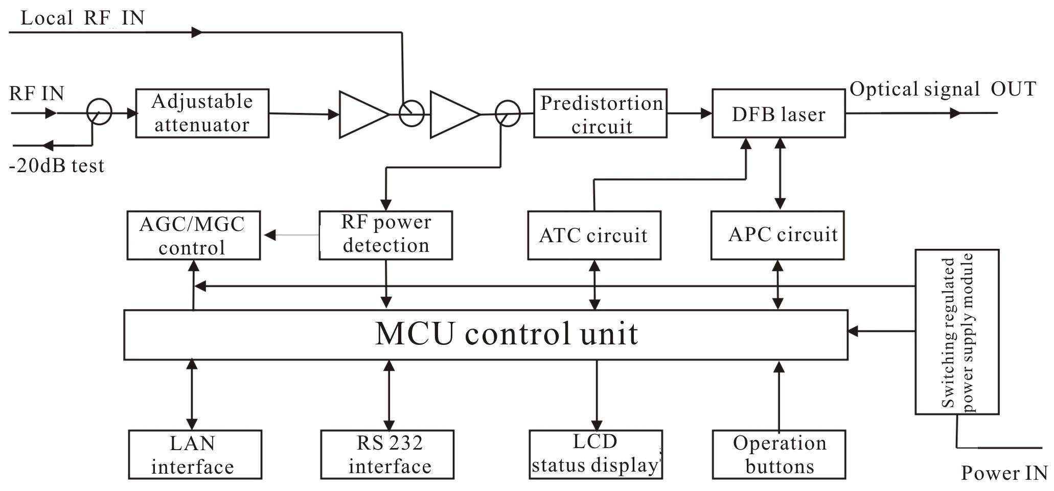
1550nm直接変調光送信機ブロック図
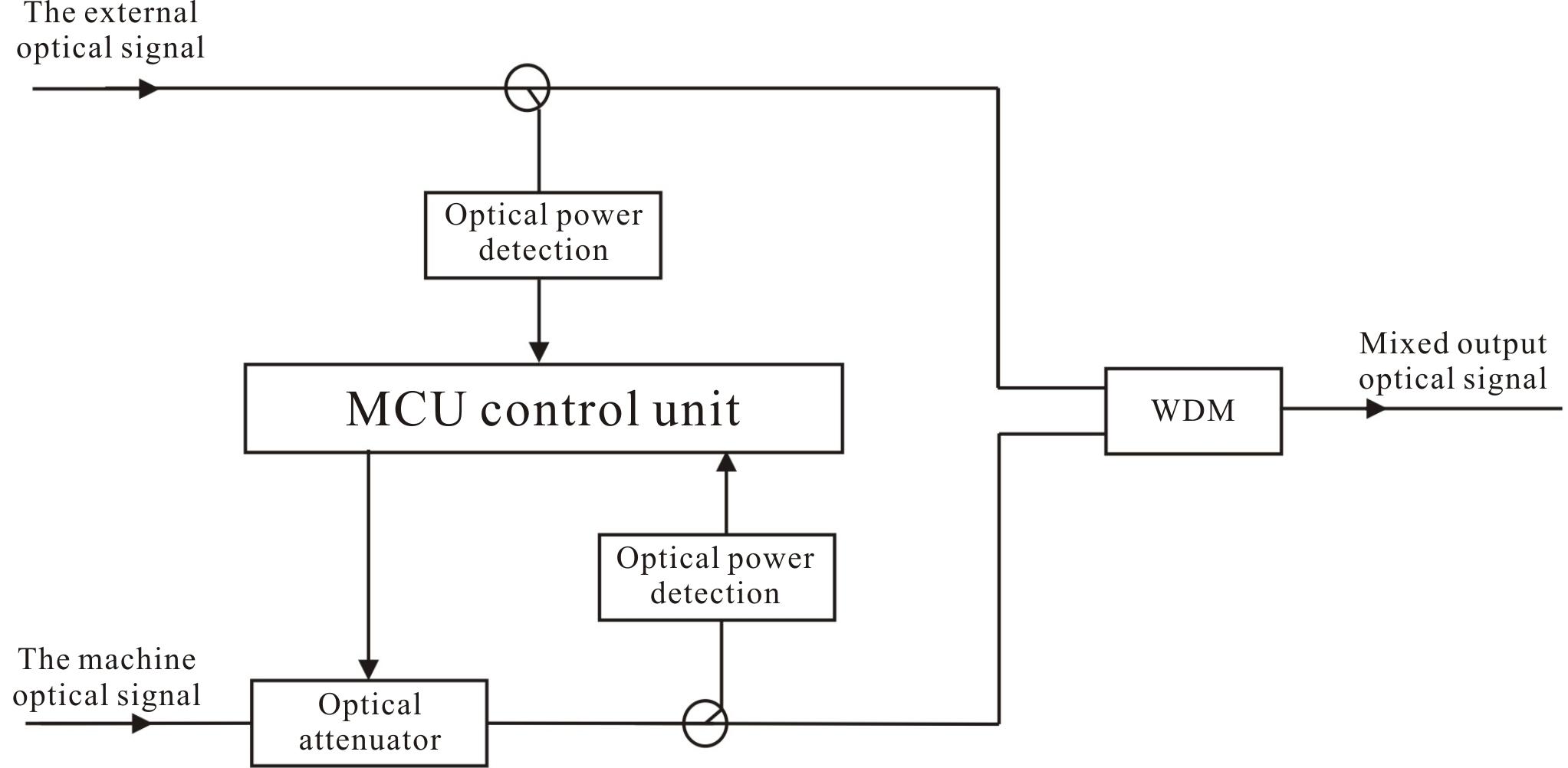 インターカット部品ブロック図
フロントパネル
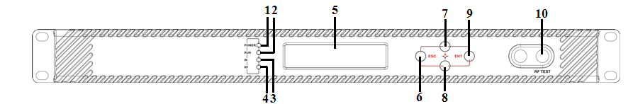
フロントパネルの回路図
|
1 |
Power indicator |
2 |
Running indicator |
3 |
Laser indicator |
|
4 |
RF input indicator |
5 |
LCD |
6 |
ESC key |
|
7 |
UP key |
8 |
DOWN key |
9 |
Enter key |
|
10 |
RF output test port |
11 |
Laser switch |
|
|
指標の説明
|
Power indicator (POWER) |
Power on |
LED green |
|
Running indicator (RUN) |
Run normally |
LED flash green |
|
Laser indicator |
Laser OFF |
LED red |
|
Laser ON |
LED green |
|
RF input indicator (RF) |
No output or exceed the normal range |
LED flash red |
|
Normal |
LED green |
背面パネル

背面パネル回路図
|
No. |
Name |
Remark |
|
1 |
Fan |
|
|
2 |
RF input |
|
|
3 |
Local RF input |
Generally reserved |
|
4 |
Ground stud |
Used for the connection of device and ground wire |
|
5 |
Optical input |
Inserted optical signal input (without inter-cut function, no this port) |
|
6 |
Optical signal output |
This interface is the optical signal output port of the device (If select inter-cut function, this port is mixed output) |
|
7 |
RS232 interface |
Used for configuring the network management parameters. |
|
8 |
LAN interface |
Correspond to IEEE802.3 10Base-T, used for network management. |
|
9 |
Switching power supply |
Hot plug |
.webp)


")