

.webp)


Introduction
CWDM Transceivers are optical transceivers based on the CWDM (Coarse Wavelength Division Multiplexing) technology. They are particularly useful when operating bidirectional (BIDI) links, since each site comprises a transmitter in addition to a receiver. Laser, receiver diode, and relevant electronics for driving the laser and shaping the received signal are built-into a module having a standardized interface. Another powerful feature of those transceivers is their modularity, that is, the ability to plug the transceivers into electronic circuit boards and to interchange them. This modualarity allows separation of the optics from the electronics area of the systems and therefore support a cost-effective system design. One of the requirements with this modularity is the adoption of common standards for transceivers.
CWDM Technology Overview
First of, let's possess a talk about the CWDM technology. There are two main kinds of WDM (Wavelength Division Multiplexing) technology being used for multi-service metro-access/enterprise applications, namely DWDM (Dense Wavelength Division Multiplexing) and CWDM. The key differences between these two variants result from their unique channel allocations within the fiber spectrum, which give rise to specialized component technologies, price-points, and applications. Generally, CWDM offers lower price-points as compared with DWDM and hence is extremely amenable to many cost-sensitive access and enterprise applications. Facts are now presented (shown in the table below).
| Feature | CWDM | Metro DWDM |
| Wavelengths per fiber | 8-16 (O, E, S, C, L bands) | 40-80 (C, L bands) |
| Wavelength spacing | 2500 GHz (20 nm) | 100GHz (0.8 nm) |
| Wavelength capacity | Up to 2.5 Gpbs | Up to 10 Gbps |
| Aggregate fiber capacity | 20-40 Gpbs | 100-1000 Gbps |
| Laser transmitter types | Uncooled DFB | Cooled DFB, external mod |
| Filter technology | Thin film | Thin film, AWG, Bragg gating |
| Transmission distances | Up to 70 km | Up to 900 km |
| Overall cost | Very low | Medium |
| Applications | Enterprise, metro-access | Access, metro-core, regional |
1. Fiber Spectrum Allocation
Within the metro and access arenas, Single Mode Fiber (SMF) is definitely the most commonplace, most particularly SMF-28 type fiber. Over a period of time, a growing number of spectral "bands" have been delineated in order to exploit the useable bandwidth with this particular fiber, consistent with growing traffic demands and advancing component technologies (begin to see the figure below). Originally, SMF was created to "optimize" single-channel operation within the 1310 nm region, widely referred to as the "O-band", and consequently many early "legacy" SONET/SDH and Ethernet products specified for to operate herein. In this area, SMF exhibits zero dispersion and incredibly moderate loss (approximately 0.35 db/km).
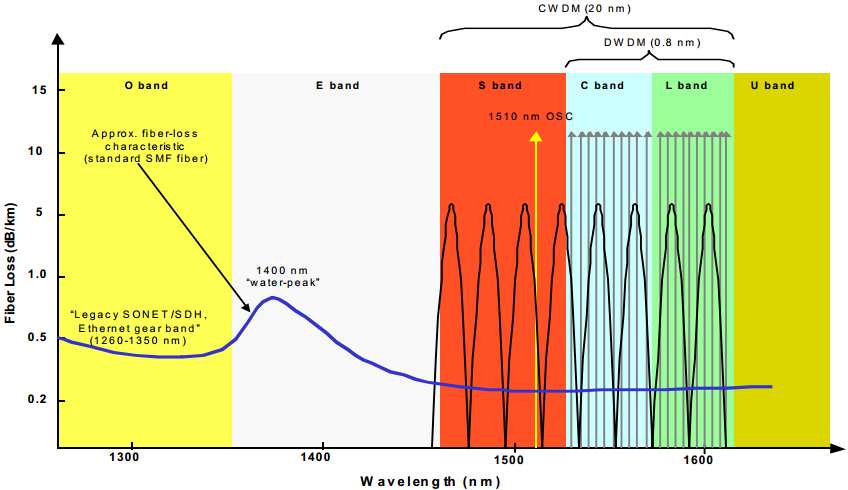
Early on, single-channel (O-band) transmission was extremely effective in extending legacy SONET/SDH and Ethernet over large distances. However, as these systems only supported just one transmission channel per fiber, they became increasingly (fiber) inefficient for operators facing surging traffic demands. As a result, designers began to look at expanding transmission capabilities into additional (SMF) spectral regions to be able to better utilize existing fiber capacity/resources. This essentially resulted in the creation of new transmission bands along with a move toward multi-channel transmission, namely WDM. Now considering the overall profile of SMF, naturally any new transmission bands could only be placed where loss and dispersion figures were acceptably low. It's here that designers chose to move upwards in to the 1500 nm region, because the 1375-1400 nm region (E-band) exhibits high attenuation due to light energy absorption by residual water vapor, i.e., "water-peak" at 1383 nm. This transmission band expansion has resulted in the emergence of DWDM and also CWDM.
The basic premise of CWDM technologies are to offer acceptable optical bandwidth scalability at extremely reduced price points. These objectives are achieved by defining much broader channel spacing, typically 2500 GHz (20 nm), within the available SMF spectral bands, thereby helping curtail related component stringencies and costs (as detailed in subsequent section). Most current CWDM components cover the C and L band region (similar to DWDM) and also be employed in part of the S band (1460-1530 nm range) and yield as much as 8 wavelength channels (Figure 2). However, in an effort to further expedite component standardization and vendor interoperability, the ITU-T has recently started work on defining CWDM bands and related channels (much like DWDM ITU-T grid). Here channel spacing is placed to 20 nm (as expected) and the related transmission spectrum is expanded to include the O and E bands (in addition to the currently-used S, C, and L bands). Adding the O and E bands is specifically meant to exploit the additional capacity available on new "metro-optimized" fibers. Using these provisions, CWDM will deliver ample capacity scalability and unrivaled wavelength economics, an ideal combination for metro-access and enterprise settings.
Many optical component vendors today already have significant CWDM portfolios on the market. In particular, there are many key technologies which are helping lower overall network costs and accelerate the deployment of CWDM paradigms. Generally speaking, these include lower-cost lasers, wideband optical filters, as well as "metro-optimized" fibers. However, continuing advances are delivering improved price-performance ratios, inevitably furthering the situation for CWDM technology. Some facts are now presented.
2. Enabling Technologies
Most WDM-based systems today utilize distributed feedback laser (DFB) sources, effectively covering distances as much as 100 km (SMF-28). However, these units exhibit temperature-based frequency variation and frequently up to 6 nm variation can be expected over a broad operating range of 0 to 70 ℃ (i.e., about 0.08 nm/℃). Clearly, this degree of fluctuation is extremely high for narrow DWDM spacing, and therefore complex monitoring and cooling circuitry is required to maintain narrow passbands for DWDM, adding significantly to DWDM system costs. Conversely, wider-channel CWDM applications don't pose such restrictions and may make use of much lower-cost uncooled DFB lasers for bit rates as much as 2.5 Gbps. Specifically, 20 nm spacing can certainly handle temperature drift ranges, leaving nearly 13 nm bandwidth for user bandwidth. This setup precludes expensive temperature control circuitry, reducing costs significantly and also yielding reduced power dissipation, e.g., only 1-2 W typically per channel versus over 10 W for larger DWDM lasers. Moreover, unlike DWDM, CWDM does not have any provisions for optical amplification which further reduces costs. Although the lack of CWDM amplifiers affects span distances, non-amplified transmission is much more than adequate for many metro-access/enterprise settings, since over 90% of metro-area rings in The united states are under 100 km in perimeter. In most, the above features also enable much more compact laser packaging, up to 70% smaller than DWDM lasers, that is ideal for enterprise applications where footprint considerations are important.
Wideband optical filtering devices are another key provision for WDM systems and are used to implement channel multiplexing/demultiplexing operations from fiber cables. Today, most WDM filters derive from thin-film technology, which utilizes a manufacturing-based layering process to achieve differing channel separations. Specifically, the amount of filter layers increases with finer channel spacing and typical DWDM filter elements require about 150 layers. On the other hand, wider CWDM grid spacing (2500 GHz) reduces the number of filter layers to around 50, and this yields a very significant reduction in manufacturing costs. Consequently, today most CWDM filters are nearly 50% cheaper than their DWDM counterparts, and in addition both variants still show steady price declines. Overall, most commercially available CWDM filters operate in the 1470-1610 nm band and may extract as much as 8 wavelength channels. However, since various cable manufacturers are now offering new, specialized fiber types with an increase of transmission capacity, future CWDM filtering devices will probably offer expanded channel coverage.
CWDM Transceivers Overview
Then, we come to the key point that is the transceiver. Combining transmitter and receiver into a single device leads to the concept of the transceiver. As mentioned above, CWDM transceivers are based on the CWDM technology. The transceiver revolutionized many areas of optical communications, and the standards involved as well as recent developments are presented following.
1. Evolution of the Optical Transceiver
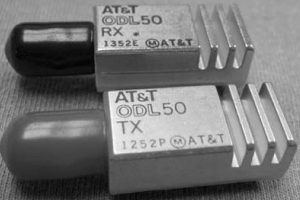
The transceiver, a combination of transmitter and receiver in a single device, is one of the key buliding blocks in optical transmission systems. Historically, optical transceivers grew out of system line cards where the sources and detectors were combined with the appropriate electronics to launch signals into fiber in the case of the receiver. An example for early transmitters and receivers is shown in the picture below. The presence of transmitter and receiver in pairs facilitates the design of BIDI fiber links. In its simplest case, the BIDI transmission is achieved with two separate fibers; each fiber carries a signal in one direction. In this case, the two directions are totally independent and due to the absence of crosstalk, the wavelength allocation for the two directions can be done separately. The concept of BIDI transmission also works for a single fiber. Here, the crosstalk between channels can be minimized to operate the BIDI link at different wavelengths. The figure below shows the basic duplex fiber optic transmission system based on transmitter and receiver pairs.
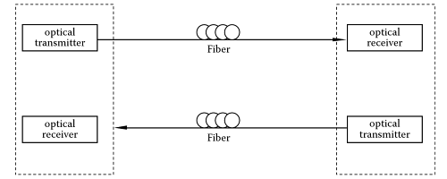
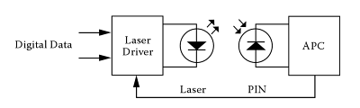
The system in the above figure consits of the transmitter, optical fiber, and a receiver. In order to achieve duplex transmission, there needs to be a transmitter and a receiver at each end; thereby enabling data to be sent to and from each location. The earliest implementation of transmitters and receivers were realized on circuit boards. These devices were built from discrete components and placed on a circuit board along with other circuitry to process the signals, provide power, etc. As the volume and speed of transmission increased, there was a push to integrate the functionality of the transmitters and receivers onto a single module. The basic building blocks for an optical transmitter are the source and the driver circuitry for modulation. The digital receiver consists of a detector, amplifier, and comparator.
2. Uncooled Transmitters for CWDM
The main difference between DWDM systems and CWDM systems with regard to the electro-optics is the use of cooled DFB lasers as sources in DWDM systems and the use of uncooled DFB lasers as sources in CWDM systems. As a result, the CWDM transmitter is simplified.
No integration of TEC (ThermoElectrical Cooler) and cooler required Less complexity for control electronics Reduced power consumption, only laser diode current required Smaller footprint Lower device cost
Direct modulation of simple transmitters results in broadened linewidth Laser wavelength drift needs to be accommodated Temperature-induced output power variation needs to be small
Tips about the wavelength drift:
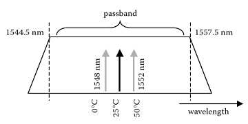
The figure below shows the wavelength drift of an uncooled single frequency DFB laser within the passband of a standard 13-nm wide CWDM multiplexer filter. Typically, the operating temperature can vary from 0 to 70°C, thus resulting in a wavelength variation up to 7 nm. Therefore, it is crucial that the CWDM systems design can accommodate the wavelength shift without any loss in performance. As a consequence, the filters have to be sufficiently wide, with a flat top characterstic across the entire passband.
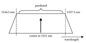
The ITU-specified center wavelengths of the CWDM filters are positioned at 1511, 1531, 1551, 1571 nm, etc. However, the nominal wavelengths of the CWDM lasers are 1510, 1530, 1550, 1570 nm, etc. The reason the filters are offset by 1 nm is to accommodate the typical temperature rise accociated with number, the variation between ambient outside temperature and the ambient temperature found inside the enclosure can be large or small, depending on design and operating conditions. The relationship between the center of the passband and the edges of the filter is summarized in the figure besides.
3. Optical Receivers for CWDM
Basic optical receivers consist of two units: detection and amplification. The functional blocks of a receiver are shown in the figure below where the photodetector as the optical front-end converts incoming light into electrical data signals. Depending on the type of detector, we can calssify two types of receivers: either PIN-based receivers or APD-based receivers. Following the detection, the amplification part of the receiver is designed to restore the original data, often together with a clock signal derived from the data. The receivers we consider here use direct detection and are working with the Non-Return to Zero (NRZ) modulation format. Other, often more complicated receiver concepts are used, which are further described in the literature.

Allow an increased link budget and therefore enable unamplified transmission with large fiber and component loss budget and thus ideal for CWDM Ideal for detection of wavelengths were no optical amplifiers are available or when transmission line costs have to below Sensitivity better than -30 dBm for 2.5 Gbps, -24 dBm for 10 Gbps receivers
The PIN diode for detection at most bit-rates, including 10 Gbps and more; however, most common is 1.25 to 2.5-Gbps operation for CWDM Mostly used for low-cost receivers where less sensitivity than APD can be tolerated, for example, -16 dBm at 10 Gbps, -22 dBm at 2.5 Gbps Compact receivers with low-noise electrical amplifiers, limiting amplifier often integrated
4. CWDM Transmission Link
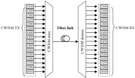
In this example, transmitters and receivers are used to build the standard CWDM transmission link comprising of 16 channels between 1310 and 1610 nm. Each of the channels requires a transmitter receiver pair as shown in the figure for a conventional, unidirectional link, that is, where all the signals are transmitted parallel from left to right. All channels typically operate at either 1.25 Gbps or 2.5 Gbps, although different bit-rates might occur. The DFB lasers are directly modulated with a 1.25/2.5-Gbps NRZ sequence with a typical ER of 8 dB. The lasers are uncooled and their wavelengths fall within the passbands of the multiplexer/demultiplexer (MUX/DEMUX) components. After transmission over the fiber link, the channels are demultiplexed and individually detected.
5. CWDM Transceiver Building Blocks
CWDM transceivers typically use DFB lasers for performance and PIN diodes for simplicity and cost. The transceivers are board mounted so that they electrically directly interface the board electroincs. At the optical interface, optical connectors are used that conveniently snap in and allow a simple yet reliable connection to the transmission fiber or other optical components. The connectors are in general standard LC or SC-type connectors.
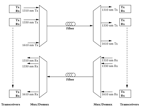
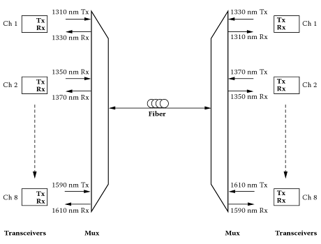
The 16 transmitters and receivers are replaced by transceivers, resulting in 16 transceivers at each side and two separate fiber. Consequently, the unidirectional 16-channel reference system in the figure is doubled with now a total of 32 channels transmitted over two fiber. At each side, 8 transceivers are used with only a single fiber. In this case, there are only small changes compared to the 16-channel reference link. Only one fiber carries BIDI traffic and no additional multiplexers (MUXes) are required. At each side, 8 transceivers are used where half of the 16 wavelengths propagate left-right, for example, 1310, 1350, 1390 nm, etc., while the remaining wavelength, 1330, 1370 nm, etc., propagate in the other direction. Other channel plans are also possible where the lower 8 channels up to 1450 nm propagate in one direction and the other direction uses the longer wavelength channel up to 1610 nm accordingly. Alought a single fiber is used, the crosstalk among channels is negligible. Unlike the case discussed earlier, only half of the capacity is reached but, on the other hand, the amount of new equipment is considerably reduced to just replacing the discrete transmitters and receivers with the transceiver modules. An implementation of the discussed scheme with a total of 16 transceivers is shown in the figure.

6. CWDM Transceiver Standards
CWDM SFF (Small Form Factor): The SFF was one of the first commercially available small form transceivers that used only half the space of the popular conventional SC types. CWDM SFF transceivers found their way into applications ranging from 100 Mbps all the way up to 2.5 Gbps.
Bulk Fiber Optic Cables OM3, OM4 Fiber, Tight Buffer, Indoor & Outdoor, LSZH, Figure8, ADSS Fiber Cables |
Fiber Optic Patch Cables 10G Patch Cable, Single Mode, Multimode, Armored, MPO/MTP Turnk Cables, & Pigtails |
Fiber Optic Transceivers SFP, SFP+, XFP, XENPAK, DWDM, CWDM, 40G QSFP+ & CFP Modules |
-consulting for technical supports or relevant product buying guide
Email for Sales

No comments have been posted yet.