

.webp)


Optical transmission system, also called fiber optic network, is at the very core of most modern telecommunications systems. It offers both unprecedented capacity and the deployment flexibility needed to support a wide range of evolving and emerging broadband applications. Especially the development of WDM technology, which considerably reduces the cost of optical transmission system and promotes the advance of optical transmission. This paper will help you to understand the optical transmission system through explaining the classification of it.
Key Optical Component of Optical Transmission System
This section describes the basic optical components used in an optical transmission system. An exemplary optical network identifying the key optical components is shown in the following picture. The end-to-end optical transmission involves both electrical and optical signal paths. To perform conversion from electrical to optical domain, the optical transmitters are used, while to perform conversion in opposite direction (optical to electrical conversion), the optical receivers are used. The optical fibers serve as foundation of an optical transmission system because the optical fiber is used as a medium to transport the optical signals from source to destination. The optical fibers attenuate the signal during transmission, and someone has to use optical amplifiers, such as erbium-doped fiber amplifiers (EDFAs), Raman amplifiers, or parametric amplifiers, to restore the signal quality. However, the process of amplification is accompanied with noise addition. The simplest optical transmission system employs only one wavelength. The wavelength division multiplexing (WDM) can be considered as an upgrade of the single-wavelength system. WDM corresponds to the scheme in which multiple optical carriers at different wavelengths are modulated by using independent electrical bit streams, and then transmitted over the same fiber. WDM has potential of exploiting the enormous bandwidth offered by the optical fiber. During transmission of WDM signals, occasionally one or several wavelengths are to be added or dropped, which is performed by the optical component known as optical add–drop multiplexer (OADM). The optical networks require the switching of information among different fibers, which is performed in optical cross-connect (OXS). To combine several distinct wavelength channels into composite channel, the wavelength multiplexers are used. On the other hand, to split the composite WDM channel into distinct wavelength channels, the wavelength demultiplexers are used. To impose the information signal, optical modulators are used. The optical modulators are commonly used in combination with semiconductor lasers.

An exemplary optical network identifying key optical components
Optical Transmission System Classification
The optical transmission systems can be classified according to different criterions. In this section, we will explain the classifications of optical transmission systems from several aspects.
By Operating Wavelength Range
A wide range of the optical system operating wavelengths can provide a very high capacity for the optical transmission system. The optical fiber type, source characteristics, system attenuation rang and dispersion of the optical path decide the operating wavelength range.
Singlemode fiber system spectral bands in ITU Recommendations:
| Band | Wavelength Range | Description |
| O-band | 1260 nm -1360 nm | Original Band - Cable cut-off wavelength decide the lower limited wavelength is 1260 nm. The upper linit 1360 nm was chosen as to the rising edge of the “water” attenuation band peaked at 1383 nm |
| E-band | 1360 nm -1460 nm | Extended Band - Recommendation ITU-T G.652 also includes fibers with a low water attenuation peak, which allows the utilization of the band above 1360 nm. The effects of a small water peak are negligible at wavelengths beyond about 1460 nm |
| S-band | 1460 nm - 1530 nm | Short Wavelength Band - The lower limit of this band is taken to be the upper limit of the E-band. The upper limit is taken to be the lower limit of the C-band. EDFAs have become available with relatively flatter and wider gains and application of EDFAs to this band is possible at least in a part of the band. Some wavelengths of this band may also be utilized for pumping of optical fiber amplifiers, both of the active-ion type and the Raman type |
| C-band | 1530 nm - 1565 nm | Conventional Band - Initially, erbium-doped fiber amplifiers (EDFAs) had useful gain bands beginning at about 1530 nm and ending at about 1565 nm. This gain band had become known as the "C-band" |
| L-band | 1565 nm - 1625 nm | Long Wavelength Band - For the longest wavelengths above the C-band, fiber cable performance over a range of temperatures is adequate up to 1625 nm for current fiber types |
By Fiber Modes
According to fiber modes, optical transmission system can be devided into two types: multimode optical transmission system and singlemode optical transmission system. The former is used the multimode fiber as the network trunk, and limited by the transmission frequency, thus, it is generally used in 140Mbit/s transmission systems. In contrast, the singlemode optical transmission system is used the singlemode fiber cable. It has a larger capacity and can be used in long distance transmission. It is widely used in nowadays optical tranmission system.
By Optical Transmission Model
At present, there are two basic optical transmission model, one is analog optical transmission system and other one is digital optical transmission system. Analog optical transmission system directly intensity-modulates the source through analog signals, whlile the digital optical transmission system is used PCM digital signal to directly intensity-modulate the light source. The digital optical transmission system can be used to achieve long distance transmission with high quality, and it is now widely used by people.
By Bit-rate
When bit rate is used as classification criteria, the optical tranmission system can be classified as low-speed (tens of Mb/s), medium-speed (hundreds Mb/s), and high-speed (Gb/s).
By Optical System Interfaces
Single-channel interface has only one optical channel or wavelength present on an optical fiber, while multichannel interface has several optical wavelengthes present on an optical fiber. A multichannel system is generally described as a wavelength division multiplexing (WDM) system.
Classifications of WDM Transmission System
WDM is the core technology of today's optical transmission system. When talking the classification of optical transmission systems, it is necessary to mentioned WDM system. WDM system can be classified according to its features, number of channels, or transmission directions.
By Features
By Number of Channels in WDM System
Number of channels in DWDM systems
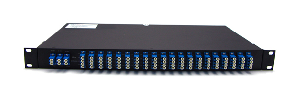
Fiber-Mart DWDM MUX DEMUX
|
In Recommendation ITU-T G.694.1, which provides the definition of frequency grids to support dense wavelength division multiplexing applications, currently four specific frequency grids are defined: 12.5 GHz spacing, 25 GHz spacing, 50 GHz spacing and 100 GHz spacing. All the four frequency grids include 193.1 THz (1 552.52 nm) as one of their members, and there are no frequency limits beyond which the grid is not defined. This grid in fact is a "ruler" with no limits or end points. Clause 6.2.2.1 of Supplement 39 to the ITU-T G-series Recommendations summarizes the above four frequency grids. In addition it shows that, using a specific formula, all the possible channel frequency grids can be derived. Additional, wider spacing frequency grids can be used by taking integer multiples of 100 GHz spacing, i.e. 200 GHz, 300 GHz, 400 GHz, etc. The grids for these wider spacings are intentionally not specified to provide the user with complete freedom for choosing central frequencies. |
ITU-T Recommendations defining applications that utilise these DWDM frequency grids include Recommendations ITU-T G.692, ITU-T G.698.1, ITU-T G.698.2 and ITU-T G.959.1. The number of channels is not specified, but, as an indication, about 40 channels with 100 GHz spacing (100 GHz × 40 ch. =4,000 GHz = 4 THz) can occupy the complete C-band of 1 530-1 565 nm. Of course, the number of channels can double when using a channel spacing of 50 GHz.
Number of Channels in CWDM systems

Fiber-Mart CWDM MUX DEMUX
|
Recommendation ITU-T G.694.2 provides the definition of a wavelength grid with channels spaced at 20 nm to support coarse wavelength division multiplexing applications. This CWDM grid has been initially defined to allow simultaneous transmission of several optical 2.5 Gbit/s signals with sufficient separation to permit the use of uncooled sources. The channel spacing of 20 nm was determined mainly by three factors:
the laser manufacturer is allowed a wavelength variation around the nominal wavelength in order to achieve a higher yield and/or relax manufacturing tolerances the laser wavelengths are allowed to change over a sufficiently wide temperature range to permit usage of uncooled lasers a sufficiently wide guardband is left between the channels to allow the use of low cost filter technologies
|
By Transmission Direction
According to the transmission direction, WDM system can be divided into two types:
Uni-directional WDM vs Bi-directional WDM
Fiber-Mart is a professional manufacturer and supplier of optical networking products. If you have any demands in your optical transmission network, Fiber-Mart is your best choice. We promise to offer the most perfect solution for you. For more information about optical transmission system or WDM system, please contact us.
FTTX Filter WDM Supply Customize FWDM Module to fit your specific requirements |
SDH Optical Amplifiers Booster Amplifier, in-line Amplifier, Pre-Amplifier for SDH networks |
WDM Transponder (OEO) SFP to SFP, SFP+ to SFP+, XFP to XFP, SFP to XFP, QSFP to QSFP OEO Transponder. |
-consulting for technical supports or relevent product buying guide
Email for Sales


No comments have been posted yet.