
.webp)


|
Recent Order
|
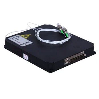
Optical Switches Mini 1x4 Opto-Mechanical, Non-latching 5V (Latching, 3V optional)
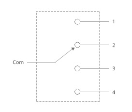
The Mini 1x4 Opto-Mechanical Optical Switches Bi-directional Fiber Optic Switch connects optical channels by redirecting 1 incoming optical signals into 4 output fibers. This is achieved using a opto-mechanical configuration and activated via an electrical control signal. The switch has integrated electrical position sensors.Based on thin film filter technology that provides a robust method of altering the light patch, this series of products has a drastically simplified platform configuration offering high reliability and low production cost. This novel design significantly reduces moving part position sensitivity, offering unprecedented high stability as well as an unmatched low cost.
Specifications
Note: Optical Route
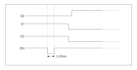
Timing Diagram
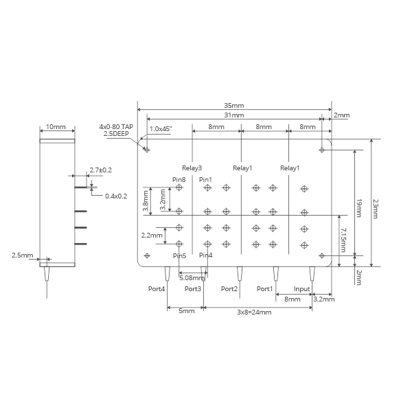
Mechanical Dimensions (Unit: mm)
Electrical Driving RequirementsThe load is a resistive coil which is activated by applying 5V (draw ~ 40mA). Applying too long pulse for the latching version will heat up the device. Fiber-Mart also offers TTL, USB, and RS232 interfaces as an option-please contact Fiber-Mart sales at [email protected].
Order information: OSW-1x4-A-B-C-D-E-F-G
Fiber-Mart provides customized design optical switches to meet special control and applications. Also, Fiber-Mart offers modular assemblies that integrate other components to form a full function modules or subsystem. For details, please contact Fiber-Mart at [email protected].
For example: OSW-1x4-M6-13-5-L-S-15-FP
Fibermart 1x1 Mechanical Optical Switch Datasheet
Fibermart 1x2 Mechanical Optical Switch Datasheet
Fibermart 1xN Mechanical Optical Switch Datasheet 2025
Fibermart 1x64 Mechanical Optical Switch User Manual 2025
Fibermart 1xN MEMS Optical Switch Datasheet 2026
Fibermart 1xN MEMS Optical Switch User Manual 2026
Fibermart 2x2 Mechanical Optical Switch Datasheet
Fibermart 2x2B Mechanical Optical Switch Datasheet
Fibermart 1xN PM Optical Switch Datasheet
Datasheet to Download Add your TagsOptical Switch | Opto Mechanical | 1x4 Optical Switch |Customized Service :
● If you need any customized products or services, please write your request in Order Remarks, or send an email to [email protected].
Get Quote or Checkout Online :
● To request a Quote or Checkout to pay online, simply add items into your cart and select your preferred method.
Free Shipping & No Tariff :
● Online Order over US$200 is Free Shipping (Not included Heavy Items like Outdoor Cable, Outdoor Cabinet etc), ● For US customer, Fibermart covers all customs duty and fees - no additional tariff charges.
Shipping Time :
● FedEx : 2-4 business days
Payment Method :
● PayPal (Online) ● Credit / Debit Card (Online) ● ABA Routing (US Local)
● T/T Wire Transfer (International) Returns & Warranty :
● 1-Year Warranty ● 60-Day Returns ● 60-Day Exchange ● Limited Lifetime Warranty. Read full Return & Refund Policy
Net Term & Credit :
● Fibermart accept Net 30 and Net 60 payment terms, Contact Us for Credit Account by submit a credit form.
Volume Discount :
● Fibermart offers discount prices for large-volume order, Contact Sales Team for more details.
Customer Reviews Displaying 1 to 2 (of 2 reviews)
by Anika Kovac
Date Added: 10/15/2025
Very sensitive optical switch with low insertion loss and crosstalk came from Fibermart brought us a great user experience. Rating: by Joshua Andre
Date Added: 02/28/2020
They connect easily and firmly. No communication issues and work flawlessly with my project. I’ve only had this a short time, but so far so good! Rating: Recently ViewedRecommended products |