

.webp)


Fiber Optic Splice Closure
Fiber Optic Splice Closure is a assembly used to offer spaces to fuse optical fiber as well as to provide protections to the fused fiber joint point and the fiber optic cables. It protects fiber optic splice while providing fast and easy no cost reentry. Inside the closure there are fiber splice trays. Optical fibers are fused and put inside the fiber splice tray for protection. Then the closure itself provides further protection.
The fiber optic splice closure is installed on wires, in manholes, in ducts, and mounted on poles. It provides reliable sealing performance and fiber splices are enclosed in a ribbed polypropylene body that has high mechanical and environmental specifications.
There are various kinds of fiber splice closures suit for different applications. They are used with aerial fiber optic cables, duct fiber optic cables and direct buried fiber optic cables. Generally, fiber optic splice closures are used outdoors, some even used underwater. Typical fiber optic splice closures include vertical type and horizontal type.
Vertical Splice Closure
Vertical fiber optic splice closure is made of excellent engineering plastics. There are 1 inlet/outlet ports, 2 inlet/outlet ports, and 3 inlet/outlet ports types, fitting different fiber optic core numbers.

Horizontal Splice Closure
Horizontal fiber optic splice closure has various models to fit up to 432 core fiber connections max. It is perfect sealed design to be waterproof and dust proof. This product features its fast and reliable sealing ability. It suits for being used in duct, direct buried and aerial fiber optic cable installations.

Both the two types are widely used in CATV, telecommunications and fiber optic networks.
How to Choose Fiber Optic Splice Closure for Cable Installation
Firstly, make clear what kind of installation it is. Aerial installation or buried installation, and so forth?
Then, think about your splice count and splice type. How many fiber splices does the closure need to hold? Fusion splices, mechanical splices or a combination of both? Some closures can be purchased with additional sealed ports that can be opened to accommodate new fibers that may be added in the future.
Be sure to match the closure, and the application, to the correct type of splice tray. For example, if using ribbon fiber, make sure that the closure can accommodate a splice tray that is designed for ribbon.
Ease of reentry. Many newer types of closures can be sealed without requiring sealing tape or C-cement. This makes it easy to seal the closure and also to reenter it when future work is required.
Some closures have a fitting that enables the installer to fill the sealed closure with compressed air to determine if there are any leaks. A soapy solution can be applied to seams, which will show bubbles if air is leaking out.
Fiber Optic Splice Closure Operating Process
1. Components in the Fiber Optic Splice Closure

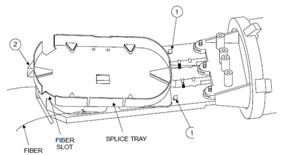
Fiber optic splice closure includes the items shown below plus additional cable attachment hardware. The cover is a cylindrical plastic enclosure with corrosion resistant metal hardware. The splice tray is used for storing optical fibers and the splice holders are used for securing fusion splices.
It accepts up to four fiber cables ranging in diameter from 10.2mm to 21.6mm in a butt configuration. It has a splice capacity of 48 fusion splices. Accessory kits are available for storing 24 mechanical splices.
It meets all requirements of the outside plant environment including aerial, buried, and underground/manhole installations.
This splice closure accepts both central tube or loose tube type fiber cables.
2. Minimum Bending Radius Requirement
As a rule of thumb, do not bend unarmored optical fiber cables to a radius of less than 10 times of its outside diameter. Armored optical fiber cables should not be bent to a radius less then 15 times of its outside diameter. Individual buffer tubes and fibers should not violate a 38-mm (1.5-inch) minimum bend radius.
3. Fiber Cable Sheath Preparation
Loose Tube and Slotted Core Cables
A. End-Sheath Preparation
If external grounding is required, trim 40 mm (1-1/2 inches) of insulation from the customer supplied 4-mm (No. 6) insulated copper wire. Coat the stripped end of the wire with a small amount of B-Sealant and insert from the outside through the ground wire hole in the grommet next to the cable. (See 5.2 Step 6.)
3.1 Expose the rip cord
1. Place a tape marker 1.0 m (40 inches) from the end of the cable.
2. Using a sharp knife, ring-cut the outer jacket at the tape marker. For metallic cables, be careful not to score the corrugated metal.
Note: Steps 3 to 5 are for metallic cables only
3. Using the knife, make a second ring-cut 16 mm (5/8 inch) from the tape marker toward cable end. This cut should score the corrugated metal.
4. Make a third ring-cut on the outer jacket approximately 150 mm (6 inches) from the end of the cable, scoring the corrugated metal.
5. Flex the cable slightly at the end to break the corrugated metal. Slide the 150-mm (6-inch ) section of outer jacket and corrugated metal off the cable core to locate the rip cord.
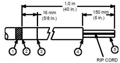
Note: Dielectric cable can go to step 6 directly
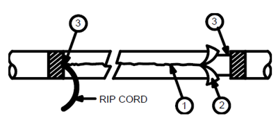
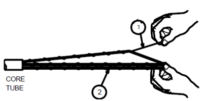
6. Use a knife to shave off the outer jacket at the end of the cable to expose the rip cord.
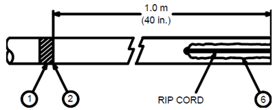
3.2 Remove the outer sheath
Metallic Cable
1. Make a 25-mm (1-inch) slit longitudinally down the outer sheath, scoring the corrugated metal. Pull the rip cord in the slit through the jacket and corrugated metal to the nearest ring cut.
2. Using a pair of pliers, peel off the outer cable jacket and corrugated metal.
3. Carefully cut the outer jacket to the ring cut at the tape marker and remove the 16-mm (5/8-inch) section of jacket.
4. Cut the rip cord flush with the end of the corrugated metal.
.png)
Dielectric Cable
5. Pull the rip cord through the jacket to the tape marker.
6. Using a pair of pliers, peel off the outer cable jacket.
7. Cut the rip cord and the dielectric strength members (if present) flush with the tape marker.

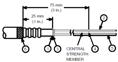
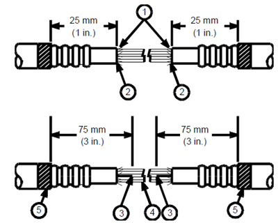
3.3 Remove the inner jacke
1. Carefully ring-cut the inner jacket 25 mm (1 inch) from the tape marker.
2. Slide the inner jacket from the cable core or use the rip cord under inner jacket to slit the inner jacket and remove it.
4. Cut the central strength member about 76 mm (or 3 inches) from the tape marker.
5. Clean the filling compound from the inner sheath, loose tubes, and central strength member.
6. Remove the tape marker.
B. Mid-Sheath Preparation
3.4 Expose the rip cord
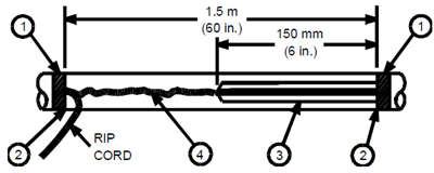
1. Place tape markers 1.5 m (60 inches) apart at the required locations on the cable.
2. Using a sharp knife, ring-cut the outer jacket at the tape markers, being careful not to score the corrugated metal if present.

Metallic Cable
3. Using the knife, make a second pair of ring cuts 16 mm (5/8 inch) inside the tape markers. These cuts should score the corrugated metal.
4. Use the knife to make another ring cut on the outer jacket approximately 150 mm (6 inches) from one of the inside pair of ring cuts, scoring the corrugated metal.
5. Using a pair of pliers, peel off the 150-mm (6-inch) section of jacket. Locate the overlap seam and peel off the 150-mm (6-inch) section of corrugated metal to expose the rip cord.

Dielectric Cable
6. Use the knife to shave off the outer jacket inside one of the tape markers to expose the rip cord
3.5 Remove the outer sheath
Metallic Cable
1. Make a 25-mm (1-inch) slit longitudinally, down the outer sheath, scoring the corrugated metal. Pull the rip cord in the slit through the jacket and corrugated metal to the other inside ring cut.
2. Using a pair of pliers, peel off the outer jacket and corrugated metal.
3. Carefully cut the outer jacket to the tape markers at both ends of the sheath opening and remove the 16-mm (5/8-inch) sections of jacket.
4. Cut the rip cord flush with the ends of the corrugated metal.
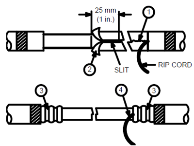
Dielectric Cable
1. Pull the rip cord through the jacket to the tape marker.
2. Using a pair of pliers, peel off the outer jacket.
3. Cut the rip cord and the dielectric strength members (if present) flush with the tape marker.
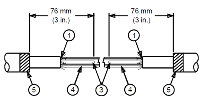
3.6 Remove the inner jacket
1. Carefully ring-cut the inner jacket 25 mm (1 inch) from the tape marker.
2. Cut the aramid yarn strands, rip cord, and core wrapping tape (if present) flush with the end of the inner jacket.
3. Cut the central strength member 75 mm (3 inches) from the tape marker.
4. Clean the filling compound from the inner jacket, loose tubes, and central strength member.
5. Remove the tape marker.
Metallic Cable
Dielectric Cable
Central Tube OSP Fiber Cables
C. End-Sheath Preparation
3.7 Expose the outer strength member wires
1. Place tape marker 1.0 m (40 inches) from end of cable.
2. With knife, ring-cut the plastic jacket at the tape marker.
3. Using a sharp knife, shave off about 150 mm (6-inch) of plastic jacket at the end of the cable to expose the strength members and rip cords.
4. Pull each rip cord through the jacket to the tape marker, splitting the jacket into two sections. Cut each rip cord flush with the marker.

3.8 Remove the plastic jacket
1. Using a pair of pliers, peel back both sections of the plastic jacket to separate it from the corrugated metal.
2. Cut both metallic strength member wires, if present, 50 mm (2 inches) from the tape marker. Carefully spread the strength member wires to gain access to the corrugated metal. Do not bend wires at this time.
3. If this is a dielectric cable, cut dielectric strength members, rip cords, and other dielectric material flush with tape marker and proceed to 3.11.

3.9 Remove the corrugated metal
1. At the seam, snip the corrugated metal 16 mm (5/8 inch) from the tape marker.
2. Open a section of corrugated metal at the cable end, exposing the inner rip cord and core tube.
3. Grip the rip cord and pull it through the corrugated metal, opposite the corrugated metal overlap, for the desired opening. Peel off the split sections of corrugated metal leaving 16 mm (5/8 inch) of the corrugated metal exposed.
4. Scrape off the plastic coating from the remaining corrugated metal.

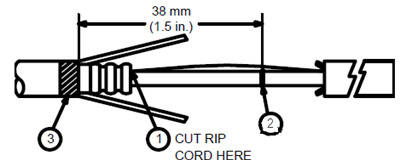
3.10 Remove the core tube
1. Cut the rip cord at the location indicated.
2. Carefully ring-cut the core tube 38 mm (1-1/2 inches) from the tape marker. Flex the core tube at the score to separate, and slide the core tube off the fibers.
3. Remove the tape marker.

3.11 Identify fiber bundles
1. Holding the fiber bundle taut, pull one binder end at a time. The binder will tighten around the fibers and then separate from the bundle. Tie the binder around the bundle, at the end farthest from the core tube, to maintain identification.
2. Using a utility wipe, remove excess filling compound from the fiber bundles.
D. Mid-Sheath Preparation
3.12 Expose outer strength member wires
1. Place tape markers 1.5 m (60 inches) apart at the required location on the cable.
2. Using a sharp knife, ring-cut the plastic jacket at both tape markers.
3. At one tape marker, use a knife and shave off about 150 mm (6 inches) of the plastic jacket over each of the two strength member wires to expose the rip cords.
4. Cut both rip cords at the tape marker where the jacket was shaved, and pull them through the jacket to the other tape marker, causing the jacket to split into two sections. Cut each rip cord flush with the tape marker.
3.13 Remove the plastic jacket
Metallic Cable
1. Using a pair of pliers, peel back both sections of the plastic jacket to separate the sheath from the corrugated metal.
2. Cut both strength member wires 50 mm (2 inches) from each tape marker. Carefully spread the strength member wires to gain access to the corrugated metal. Do not bend the wires at this time.

Dielectric Cable
3. Using a pair of pliers, peel the two jacket sections back to the tape marker. Flex the cable at the ring-cut to allow removal of the two jacket sections.
4. Cut strength members, rip cords and any other dielectric material present flush at both tape markers and go to Section 3.17.

3.14 Make preparations to remove corrugated metal
1. At the seam, snip the corrugated metal 16 mm (5/8 inch) from each tape marker.
2. At one end of the opening, measure about 100 mm (4 inches) from the tape marker and, at the seam, snip the corrugated metal. Then, remove the short section of corrugated metal to expose the core tube and rip cord.

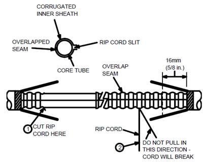
3.15 Cut the corrugated metal with the rip cord
1. Cut the rip cord at the location indicated.
2. Roll the rip cord around the nose of pliers and pull to cut the corrugated metal opposite the seam overlap. Continue cutting the corrugated metal by pulling the rip cord at a 90-degree angle. Stop at 16 mm (5/8 inch) from the tape marker. Pulling the rip cord at an angle other than 90 degrees to the cable may cause the rip cord to break.
3.16 Remove the corrugated metal
Using a light pull, separate the overlapped seam and peel off each half of the corrugated metal to 16 mm (5/8 inch) from the tape marker. Cut and remove the corrugated metal at 16 mm (5/8 inch) from the tape markers.
3.17 Remove the core tube
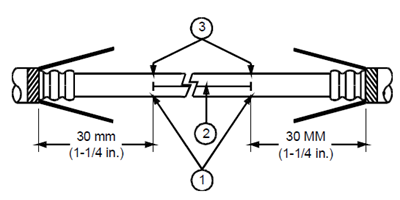
1. Mark the core tube 30 mm (1-1/4 inches) from each tape marker.
2. Carefully slit the core tube between the two marks.
3. Carefully ring-cut the core tube at both marks and remove the core tube to expose the fiber.
3.18 Identify the fiber unit(s) to be spliced
1. Select the fiber unit(s) to be spliced and cut the binder for the unit(s) at the center. While holding the fiber bundle taut, pull the binder end. The binder will tighten around the fibers and separate the unit to be spliced from the rest of the bundle. Tie the cut binder around the unit at each end to maintain identification.
2. Using a wipe, remove excess filling compound from the fiber unit(s).

4. Bonding and Grounding Hardware Installation
A. Loose Tube Cable
4.1 Bond Clamp Installation
1. Slide or place cable clamp over sheath. If corrugated metal has a plastic coating on it, use sharp knife to scrape off.
2. Slide the bond shoe under the corrugated metal until the bond shoe stud is against the corrugated metal.
3. Place the bond plate over the bond shoe. Place the sheath grip, using the center of three holes, over the bond stud and secure with hex nut.
4. Secure the sheath grip with the cable clamp oriented as shown.

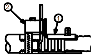
B. Central Tube (Metallic OSP) Cable
4.2 Remove the outer sheath
Place the cable clamp supplied with the closure onto the cable. Do not use the cable clamp supplied with the closure. Cut the plastic cable jacket back to leave 16 mm (5/8 inch) of corrugated metal exposed. Leave the fiberglass tape longer than the corrugated metal.

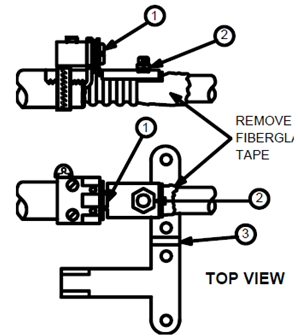
4.3 Install the wire retainer base
1. Bend the two strength members 90 degrees to the cable.
2. Apply anti-seize lubricant to the wires or wire bundles for corrosion protection.
3. Position the base of the wire retainer over the cable and between the two OSP wires. Wires should lie in the notches of the wire retainer.

.png)
4.4 Secure the wire retainer base
1. Place sheath grip member on sheath as shown.
2. Slide the cable clamp over the wire retainer and sheath grip with the clamp screw located at the side of the wire retainer base. Tighten the cable clamp screw to secure the wire retainer and sheath grip to the cable.
3. If the corrugated metal has a plastic coating, use a sharp knife to scrape the coating off, exposing the bare metal.
4. Cut off the wire or wire bundles extending from the upright leg of the wire retainer as close as possible to the wire retainer.

4.5 Install the Bond Shoe
Slide the bond shoe between the corrugated metal and the fiberglass tape until the bond shoe is against the end of the corrugated metal. The bond shoe must be lined up with the wire retainer.

4.6 Position the bond plate and block
1. Place the bond plate over the stud on the bond shoe. The hole in the flat leg of the bond plate must align with the hole in the wire retainer.
2. Position the bonding block (set screws pointed away from the cable) so the wire is between the bonding block and in the notches of the wire retainer.
4.7 Secure the bond plate and block
1. Insert the screw through the hole in the bond plate and the upright leg of the wire retainer. Then, using a screwdriver, tighten the screw into the center hole of the bonding block. The fiberglass tape may be cut off at this time.
2. Using the supplied hex tool, screw the hex nut onto the bond shoe stud.
3. If sheath isolation is required, use metal cutting pliers to cut the sheath grip along the indented lines in two places.
4.8 Orientation of the cable clamps
When preparing a pair of cables for installation in the same port, the clamps must be oriented.
5. Assembly of Cables to Closure
The preferable location for the two main cables is in the lower end plate port. If a third or fourth cable is required, it is easier to install it in the upper end plate port as a branch cable. This fiber optic splice closure is designed for two cables in each of its two ports. If only one cable will be installed in a port, the provided rubber grommet plug is used to substitute for the second cable.
A. Main Cables – Loose Tube and Slotted Core
5.1 Install Cables to End Plate
1. Unscrew knob and remove the grommet retainer from the end plate.
2. Position end plate assembly so the bottom port is up. Remove the three bolts securing the distribution organizer to the end plate.

3. Part 4 covers installation of sheath grip for metallic cables. Attach the sheath grip to dielectric cables using cable clamps. Position the dielectric cables so the end of the sheath is even with the back edge of the sheath grip. Tighten cable clamps.

4. Slide cables and sheath grip through the bottom end plate port aligning the four holes in the sheath grip with the four posts on the backbone. Exercise care not to bend the sheath grip.
5. Secure sheath grip to backbone using four self-tapping screws.
5.2 Grommet Installation and External Grounding
1. Apply B-Sealant inside the two cable openings in the grommet.
2. Place the grommet over the cable(s) so the narrow grommet retention lip faces toward the end plate and the grommet slits face toward the center of the end plate. The external ground holes should face out.
3. Apply B-Sealant inside the two grommet slits. Apply a coating of B-Sealant to the outside sealing surface of the grommet.
4. Using your thumbs, push the grommet into the end plate port until the grommet is flush on the outside and the grommet retainer lip exits the inside surface of the end plate.
5. If the splice does not require a third and fourth cable, the open end plate port should be plugged using the unused grommet and the grommet plugs as follows: (a) Apply B-Sealant inside the two cable openings in the cable grommet. (b) Place grommet plugs in the grommet. Apply B-Sealant inside the two grommet slits and around the outside sealing surface of the grommet. (c) Using your thumbs, push the grommet into the end plate port until the grommet is flush on the outside and the grommet retainer lip exits the inside surface of the end plate.

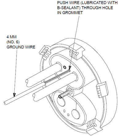
6. If external grounding is required, trim 40 mm (1-1/2 inches) of insulation from the customer supplied 4 mm (No. 6) solid insulated copper wire. Coat the stripped end of the wire with a small amount of B-Sealant and insert from the outside through the ground wire hole in the grommet next to the cable.
7. Screw the external ground connector onto the end of the 4-mm (No. 6) copper wire using the hex-tool. Remove the hex nut from the bond clamp stud and place connector over the stud. Secure with the hex nut.

8. Place the grommet retainer over the end plate and secure tightly with the knob.
9. Secure the cables to the grommet retainer using metal cable clamps to provide strain relief.

5.3 Fiber Unit Preparation and Distribution Organizer Installation
1. End-sheath splice only: Remove all loose tubes 200 mm (8 inches) from the sheath opening and clean all fibers. Identify fibers per local practice. Do not remove any loose tube(s) at this time if this is a mid-sheath splice.
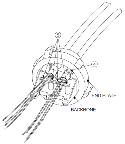
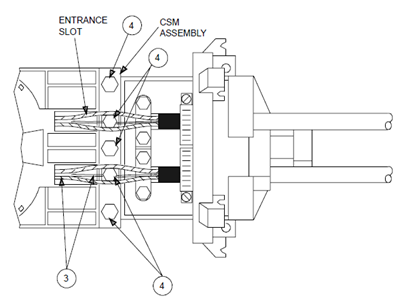
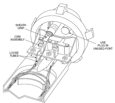
2. With the end plate and cables still in the upside down position, separate each cable’s loose tubes into two groups of approximately the same number. Loosen but do not remove the central strength member (CSM) retaining screws. Slide the CSM assembly onto the central strength members of the cables. Position the CMS assembly uprights between the two groups of loose tubes but do not tighten the retainer screws yet.
3. Position the distribution organizer upside down and place it over the loose tubes so they are captured in the entrance slots. Position the distribution organizer between the CSM assembly and the end plate backbone. Line up the holes in the parts and assemble with the three hex head bolts.

4. Tighten the three hex head bolts and the two CSM retainer screws.
5. Turn closure assembly right side up. Using the small cable ties provided, secure the loose tubes to the distribution organizer in two places. Use the outside two cable tie slots to keep the loose tubes to the outside of the distribution organizer.
6. Coil each cable’s fibers around the distribution organizer one turn and then out the rear of the tray. One cable should be coiled in one direction and the second cable’s fibers coiled in the opposite direction.
7. If this is a mid-sheath splice, locate the loose tubes containing the fibers to be spliced and carefully move them aside.
8. Coil all the remaining loose tubes around the distribution organizer and secure with several cable ties. Adjust the loose tube bundles and number of cable ties to yield a minimum cross-section of loose tubes.
9. Mid-sheath splice only: Cut the loose tubes containing the fibers to spliced in the middle. Remove the loose tubes 270 mm (10-1/2 inches) from the end of the sheath. Clean and identify the fibers per local practice.
10. Straighten the loose tube(s) containing the fibers to be spliced and secure to the loose tube bundle so the fibers extend out the rear of the distribution organizer.

5.4 Splice Tray Installation
1. Place the splice tray over the distribution organizer by engaging its two small front slots under the hooks of the distribution organizer. Feed the fibers through the slots at the rear of the splice tray.
2. Fasten the end of the splice tray to the distribution organizer by snapping the parts together.
3. If this is an end-sheath splice, THE FIBERS ARE NOW READY TO SPLICE! Proceed to Part 6. If this is a branch splice, continue to Subpart B.
B. Branch Cables – Loose Tube and Slotted Core
5.5 Install Cables, Grommet, and External Ground
1. Install branch cable in upper port of end plate using similar procedures as detailed in 5.1 and 5.2 (except 5.2 Step 5). Do not remove the distribution organizer.
2. Use the appropriate cable grommet for the size cable being installed. If only one branch cable is installed, plug the vacant port with the black grommet plug.
5.6 Fiber Unit Preparation
1. Remove the splice tray if present.
2. Remove the loose tubes 200 mm (8 inches) from the sheath opening. Remove excess cable filling compound and clean all fibers. Identify fibers per local practice.
3. Straighten the loose tubes and fasten them with cable ties to the main cable loose tube bundle so the fibers exit to the rear of the distribution organizer.
4. Place the splice tray over the distribution organizer such that it traps the branch cable loose tube(s) in the distribution organizer entrance slots. The fibers are now ready to splice. Proceed to Part 6.

C. Main Cables – Central Tube OSP
5.7 Install Cables to End Plate
Attach cables to sheath grip and install in end plate as detailed in 5.1.
5.8 Grommet Installation and External Grounding
1. Install grommet(s) as detailed in 5.2.
2. If external grounding is required, trim 40 mm (1-1/2 inches) of insulation from the customer supplied 4-mm (No. 6) insulated copper wire. Coat the stripped end of the wire with a small amount of B-Sealant and insert from the outside through the ground wire hole in the grommet next to the cable. (See 5.2 Step 6.)
3. Loosen the set screw in the bonding block and insert the ground wire into the block. Tighten the set screw to secure the ground wire into the block.
4. Place the grommet retainer over the end plate and secure tightly with the knob.
5. Secure the cables to the grommet retainer using the metal cable clamps to provide strain relief (See 5.2 Step 9).
5.9 Fiber Unit Preparation and Distribution Organizer Installation
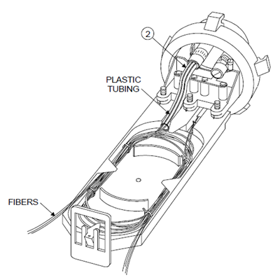
1. Select the appropriate diameter flexible tubing to fit onto core tube. Slide the 100-mm (4-inch) length of flexible plastic tubing over the fibers (if this is a mid-sheath entry, slit the tube and use small cable ties to hold together). Inject a small amount of B-Sealant into the core tube and slide the tubing over the core tube for about 15 mm (5/8 inch).
2. With the end-plate assembly upside down, turn the distribution organizer upside down and lower it over the flexible plastic tubes so they are captured in the tray’s entrance slots. Position the tray so its three holes line up with the three threaded holes in the end plate backbone.
3. Using three hex head bolts, fasten the tray to the end plate backbone. Turn assembly right side up. Using the small cable ties provided, secure the flexible tubes to the distribution organizer.
4. If this is an end sheath splice, coil each cable’s fibers around the distribution organizer one turn and then out the rear of the tray. One cable should coil in one direction and the second cable coil in the opposite direction.
5. If this is a mid-sheath splice, identify those fibers to be spliced and carefully move them aside. Coil all the other fibers around the distribution organizer. Cut the fibers to be spliced at their mid-point and feed them out the rear of the tray.

5.10 Splice Tray Installation
1. Place the splice tray over the distribution organizer by engaging its two small front slots under the hooks of the distribution organizer. Feed the fibers through the slots at the rear of the splice tray as shown in 5.4.
2. Fasten the rear end of the splice tray to the distribution organizer by snapping the parts together.
3. Fasten the tray support to the rear of the distribution organizer. If this is an end-sheath splice, the fibers are now ready to splice. Proceed to Part 6. If this is a branch splice, continue to Subpart D.
D. Branch Cables – Central Tube OSP
5.11 Install Cables to End Plate
Follow procedures as detailed in 5.1.
5.12 Grommet Installation and External Grounding
Follow the grommet installation procedures as detailed in 5.5 and external grounding (if required) procedures as detailed in 5.8.
5.13 Fiber Unit Preparation
1. Remove the splice tray if in place.
2. Select the appropriate diameter flexible plastic tubing to fit onto the core tube. Slide a 100-mm (4-inch) length of flexible plastic tubing over the fibers. Inject a small amount of B-Sealant into the core tube and slide the tubing over the core tube for about 15 mm (5/8 inch). Do not coil the fibers around the distribution organizer. Simply route the fibers out the end of the distribution organizer.
3. Place the splice tray over the distribution organizer so it traps the flexible tubing covered fibers in the distribution organizer entrance slots. THE FIBERS ARE NOW READY TO SPLICE!
6. Optical Fiber Splicing
6.1 General Instruction
1. If fusion splicing is not employed, different splice holders or connector holders will be required. See Part 10 for ordering information.
2. Sheath preparation, sheath gripping, bonding, grounding, assembly of the distribution organizer and splice trays have been described in Parts 3 through 5 depending on the cable type (Central Tube, Loose Tube, or Slotted Core) and splice type (end sheath or mid-sheath).
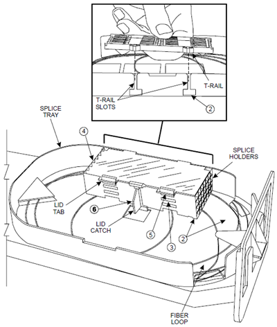
3. Note that the length of slack fiber is different for the central office (CO) cable and the field cable because of the different distances from the splice tray exit slots to the splice holder. Unlatch and remove the splice holder lid and remove all but one splice holder. Coil the slack fiber around the tray once and determine the length to the most distant splice holder splice location. This will be the maximum fiber length for this cable. Repeat the procedure for the second cable. Remove the splice holder.
6.2 Splice and Slack Fiber Storage
1. Place a splice holder in front of the closure or to its side allowing for the location of the fusion splicing equipment. Splice the fiber per local practice. Place each completed splice in the appropriate splice holder location.
2. When the splice holder is full (12 splices maximum), place the splice holder in the splice tray T-rail slots. To store a coil of slack fiber, flex the splice holder up and slide the coil under the splice holder.
3. Repeat this procedure until all fiber has been spliced, stored in the splice holders, and the slack coils stored under the splice holder stack. All four splice holders must be installed in the splice tray regardless of whether they contain splices.
4. Fasten the splice holder lid to the top splice holder by bending it slightly to engage its two hinge pins.
5. Supporting the stack with one hand, press the lid tabs until they snap into place on the top splice holder.
6. Still holding the splice holder stack, snap the lid catch onto the splice tray. Be sure no fibers are in the area of the square opening.
7. Fiber Optic Splice Closure Cover Installation
1. Clean the O-ring grooves in the cover and the end plate. Apply a thin film of B-Sealant evenly in both O-ring grooves. Seat the O-ring in the end plate groove.
2. Slide the closure assembly into the cover. Rotate the cover until its key aligns with the end plate notch. Seat the cover and secure the five latches.
3. OPTIONAL FLASH TEST: If a flash pressure test is desired, remove the plug in the end of the cover and install a suitable pressure fitting. Flash test pressure should not exceed 70 kPa (10 psi). Examine closure for leaks per local practice. Remove the pressure fitting and reinstall the cover plug using a suitable thread sealant. Use hex tool to securely seat cover plug. Do not over tighten.

8. Closure Mounting
The fiber optic closure is designed for use in aerial, buried or underground applications. The following kits are available for mounting the closure. Instructions for using each kit are covered in the following paragraphs. Note: The closure should be completely assembled before performing any mounting procedure.
A. Mounting Bracket Kit
1. Mount to wall or pole using keyhole slots. Bolts/screws are not supplied for this operation. If the bracket is being mounted vertically, make sure the arrow on the bracket is facing up.
2. Use the supplied bolts to secure the bracket to the closure mounting lugs.

B. Strand Hanger Kit
1. Loosen bolts on finger clamps and install on cable strand. Do not tighten yet.
2. Using supplied bolts, secure clamps to mounting lugs on closure.
3. Tighten all bolts.
4. Dress and lash cable to cable strand per local practice.

9. Reentry
1. Clean the closure surface to remove dirt and debris.
2. Orient the closure such that residual debris will not fall into the splice tray when the cover is removed.
3. Unfasten the five latches. Carefully slide the closure cover off.
4. Set the O-ring aside for cleaning before reassembly.
5. Perform required work.
6. Clean B-Sealant from the cover O-ring groove, the end plate O-ring groove, and the O-ring.
7. Reassemble closure per Part 7.
Bulk Fiber Optic cables OM3, OM4 Fiber, Tight Buffer, Indoor & Outdoor, LSZH, Figure8, ADSS Fiber Cables |
Fiber Optic Patch Cables 10G Patch Cable, Single Mode, Multimode, Armored, MPO/MTP Turnk Cables, & Pigtails |
Fiber Optic Transceivers.jpg) SFP, SFP+, XFP, XENPAK, DWDM, CWDM, 40G QSFP+ & CFP Modules |
-consulting for technical supports or relevent product buying guide
Email for [email protected]


No comments have been posted yet.