

.webp)


Fiber Optical Mechanical Splicing Tutorial
We have known there are two methods of fiber optic splicing, fusion splicing&mechanical splicing. Which method is better? The typical reason for choosing one method over the other is economic. If you are just beginning to splice fiber, you might want to look at your long-term goals in this field in order to choose which technique best fits your economic and performance objectives. Whatever, Let's learn more about mechanical splicing in this article.
The Concept of Mechanical Splice
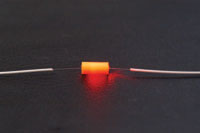
Mechanical splices are simply alignment devices, designed to hold the two fiber ends in a precisely aligned position thus enabling light to pass from one fiber into the other. A typical mechanical fiber optic splice consists of a small plastic housing with an aluminum alloy element to precisely align and clamp fibers(Figure 1). An index matching gel pre-installed at the fiber connection point maintains a low-loss optical interface, which results in a median insertion loss of less than 0.1dB. The tools to make mechanical splices are cheap, but the splices themselves are more expensive. Mechanical splices are most popular for fast, temporary restoration or for splicing multimode fibers in a premises installation. They are also used - without crimping the fibers - as temporary splices for testing bare fibers with OTDRs or OLTSs. Of course, most prepolished splice connectors use an internal mechanical splice.
.jpg)
Figure 1: On activation, the metal element in this mechanical splice grips prepared fiber ends to
hold them in permanent alignment and contact, immersed in an optical gel.
hold them in permanent alignment and contact, immersed in an optical gel.
The Types of Mechanical Splice
There are a number of types of mechanical splices, like little glass, plastic, metal, and ceramic tubes or V-shaped metal clamps or and rotary devices. Materials that assist mechanical splices in splicing fibers include transparent adhesives and index matching gels. Transparent adhesives are epoxy resins that seal mechanical splices and provide index matching between the connected fibers.
-
Glass or Ceramic Alignment Tube Splices
Mechanical splicing may involve the use of a glass or ceramic alignment tube, or capillary (Figure 2). The inner diameter of this glass or ceramic tube is only slightly larger than the outer diameter of the fiber. A transparent adhesive, injected into the tube, bonds the two fibers together. The adhesive also provides index matching between the optical fibers. This splicing technique relies on the inner diameter of the alignment tube. If the inner diameter is too large, splice loss will increase because of fiber misalignment. If the inner diameter is too small, it is impossible to insert the fiber into the tube.
Figure 2: A glass or ceramic alignment tube for mechanical splicing.
-
V-Grooved Splices
Mechanical splices may also use either a grooved substrate or positioning rods to form suitable V-grooves for mechanical splicing. The basic V-grooved device relies on an open grooved substrate to perform fiber alignment (Figure 3). When inserting the fibers into the grooved substrate, the V-groove aligns the cladding surface of each fiber end. A transparent adhesive makes the splice permanent by securing the fiber ends to the grooved substrate.
Figure 3: Open V-grooved splice.
V-grooved splices may involve sandwiching the butted ends of two prepared fibers between a V-grooved substrate and a flat glass plate. Additional V-grooved devices use two or three positioning rods to form a suitable V-groove for splicing. The V-grooved device that uses two positioning rods is the spring V-grooved splice (Figure 4). This splice uses a groove formed by two rods positioned in a bracket to align the fiber ends. The diameter of the positioning rods permits the outer surface of each fiber end to extend above the groove formed by the rods. A flat spring presses the fiber ends into the groove maintaining fiber alignment. Transparent adhesive completes the assembly process by bonding the fiber ends and providing index matching. A variation of this splice uses a third positioning rod instead of a flat spring. The rods are held in place by a heat-shrinkable band, or tube.
Figure 4: Spring V-grooved mechanical splice.
-
Rotary Splices
In a rotary splice, the fibers are mounted into a glass ferrule and secured with adhesives. The splice begins as one long glass ferrule that is broken in half during the assembly process. A fiber is inserted into each half of the tube and epoxied in place using an ultraviolet cure epoxy. The endface of the tubes are then polished and placed together using the alignment sleeve. Figure 5 is an illustration of a rotary splice. The fiber ends retain their original orientation and have added mechanical stability since each fiber is mounted into a glass ferrule and alignment sleeve. The rotary splice may use index matching gel within the alignment sleeve to produce low-loss splices.
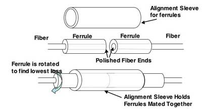
Figure 5: Rotary mechanical splice.
In shipboard applications, the Navy recommends using the rotary splice. The rotary splice is a low-loss mechanical splice that provides stable environmental and mechanical performance in the Navy environment. Stable performance means that splice loss does not vary significantly with changes in temperature or other environmental or mechanical conditions. Completing a rotary splice also requires only a small amount of training, or expertise. This shorter training time is another reason why the Navy recommends using the rotary splice over other mechanical or fusion splicing techniques.
The Process of Mechanical Splice
Step 1: Preparing the fiber - Strip the protective coatings, jackets, tubes, strength members, etc. leaving only the bare fiber showing. The main concern here is cleanliness. (Figure 6)
Step 2: Cleave the fiber - The process is identical to the cleaving for fusion splicing but the cleave precision is not as critical. (Figure 7)
.jpg)
.jpg)
Figure 6: Preparing the fiber Figure 7: Cleave the fiber
Step 3: Mechanically join the fibers - There is no heat used in this method. Simply position the fiber ends together inside the mechanical splice unit. The index matching gel inside the mechanical splice apparatus will help couple the light from one fiber end to the other. Older apparatus will have an epoxy rather than the index matching gel holding the cores together. (Figure 8)
.jpg)
(Figure 8): Mechanically join the fibers
Optional:
A Visual Fault Locator (VFL) can be used to optimize the connection. Inject light from the VFL into one of the fibers and insert the cleaved end mid-way through the splice core. This will cause the core to illuminate. Insert the second fiber into the opposite side of the splice core. When the two fiber ends are mated properly, the splice core will stop illuminating.
Step 4: Protect the fiber - the completed mechanical splice provides its own protection for the splice.
Step 4: Protect the fiber - the completed mechanical splice provides its own protection for the splice.
Featured Products
Mechanical Splice.jpg) Fast Fiber Optic Mechanical Splice for 250um bare fiber |
High Precision Fiber Cleaver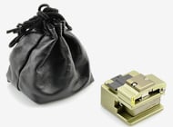 Used to cut the fiber glass to make a good end face for fiber optic splicing |
Cost-effective Fusion Splicers Various options of Fusion Splicers on Fiber-Mart |
Email for Technical Tips
-consulting for technical supports or relevent product buying guide
Email for [email protected]
-consulting for technical supports or relevent product buying guide
Email for [email protected]


No comments have been posted yet.