
.webp)


|
Product FilterClear All
Recent Order
|
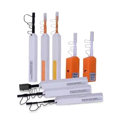
Optical AttenuatorFibermart Provides Fixed Fiber Attenuator, Variable Optical Attenuator with Stable dB Attenuation for Your Optical Network
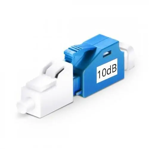
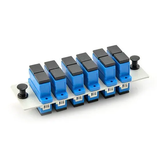
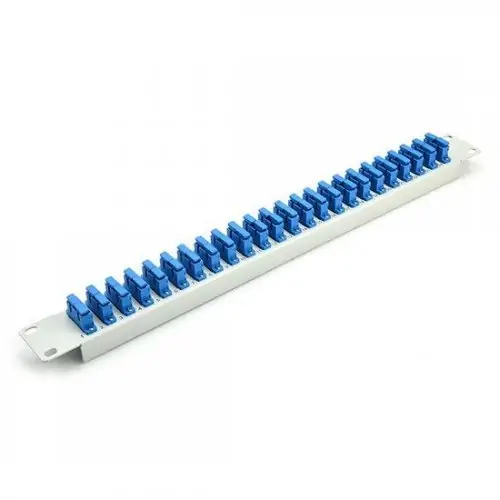
Optical Attenuator, or fiber optic attenuators, are used in optical communications to reduce optical fiber power at a certain level. Generally, the attenuator types are classified by connector types and attenuation levels. A common version is the female to male plug type bulkhead attenuator which has a connector at one side and a adapter at the other side. FiberMart provides optical attenuators with various connector types, such as FC/SC/ST/MPO/LC/E2000, available with APC or UPC polish. Our fixed attenuators can be with different attenuation levels from 1 dB to 30 dB (step by 1 dB), while the variable optical attenuators (generally used as in-line attenuators) can be with a range of 0 ~ 60 dB. Customers can buy these attenuators directly in this category or Make Customized Orders. Buy Fiber Optic Attenuator from Fiber-MART.COM
Introduction
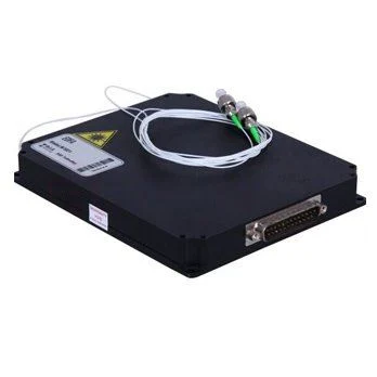
Fibermart Optical Attenuator is a precision passive device engineered to reduce and control the power level of optical signals within fiber optic networks. Essential for preventing signal overload and optimizing receiver performance, it ensures clean, distortion-free data transmission. Available in both fixed and variable configurations with a comprehensive selection of connector types (FC, SC, ST, LC, MPO, E2000) and attenuation ranges (1-25 dB fixed, 0-60 dB variable), this component provides a definitive solution for managing optical power budgets in test, measurement, and live communication systems.
Features
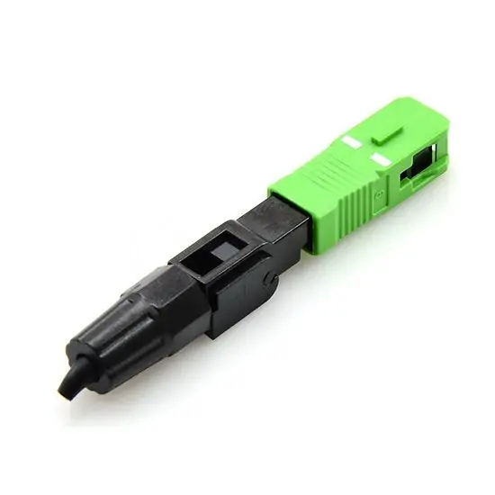
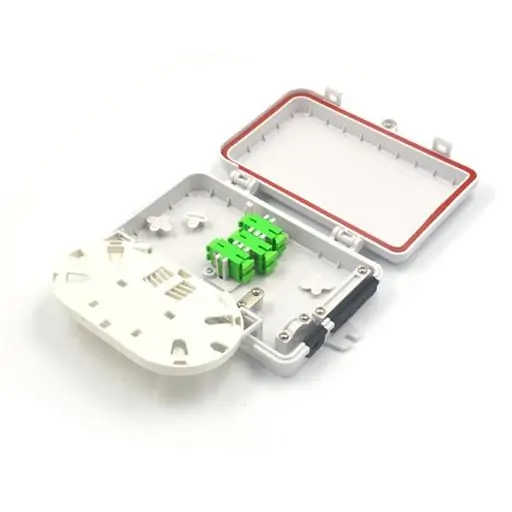
● Available with industry-standard FC, SC, ST, LC, MPO/MTP and E2000 interfaces, offered in both UPC (blue) and APC (green) types to match system requirements. ● Features fixed attenuators with precise value 1dB to 30dB (in 1 dB steps), variable attenuators with adjustable 0 to 60dB for flexible testing and tuning. ● Features connector (e.g., FC, LC) on one end and a mating adapter on the other, allow for in-line insertion between two patch cables or at equipment ports. ● Engineered for accurate, stable attenuation values with low insertion loss and high return loss to minimize signal reflection and backscatter. ● Supports customized orders for specific attenuation values, connector combinations, or bespoke form factors to meet unique project needs. ● 100% Tested with individual Testing Report, CE, RoHS, FCC, ISO9001 Certificated for each unit to ensure High performance and Zero Failure in Lifetime Warranty. ● Designed to operate effectively across standard 1310-1550nm(SM)/850-1300nm(MM) Wavelength with minimal wavelength-dependent loss.
Principles
An optical attenuator functions by deliberately introducing a controlled, repeatable signal loss into an optical fiber path. Unlike signal degradation from poor splices or bends, this loss is precise and intentional. Fixed attenuators typically use a neutral density filter or a doped fiber segment that absorbs a specific amount of light. The attenuation value is determined by the material's properties and is permanently set during manufacturing.
Variable optical attenuators (VOAs) employ more dynamic mechanisms, such as a movable neutral density filter, a gap-loss principle where the fiber ends are slightly separated, or an electronically controlled element. Adjusting the mechanism—manually via a dial or electronically via a control signal—changes the degree of light blockage or misalignment, thereby varying the attenuation level. The core principle is to reduce optical power without distorting the signal's other characteristics, such as its waveform or wavelength, ensuring the receiver operates within its ideal linear range.
Applications
● Receiver Protection in Test Labs: Preventing photodetector saturation in optical test equipment, such as power meters and OTDRs, by reducing excessively strong input signals. ● Signal Level Matching in Networks: Equalizing power levels between different channels in WDM systems or at the input of optical receivers to ensure uniform performance. ● System Power Budget Testing: Emulating channel loss during the installation and certification of fiber links to verify network design and receiver sensitivity. ● Temporary Signal Reduction for Troubleshooting: Used as an inline tool to isolate issues related to signal overload or to fine-tune system performance during maintenance. ● Telecommunication and CATV System Calibration: Ensuring optical transmitters and receivers in central offices and headends operate within specified power thresholds for optimal service quality.

|


