

.webp "Fiber Mux & OADM")


")
")


 PLC Splitter Slow Axis ABS Box PM Fiber Splitter")


Introduction of Fiber Optic Coupler, Fiber Splitter
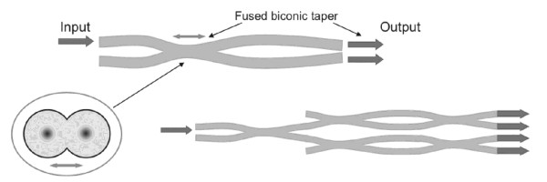
Fiber Optic Coupler is manufactured by placing two or more fibers adjacent to one another, after fusing and streching them, thus creating a coupling region. The heated area is stretched until the desired coupling properties are achieved. This device is called a fused biconical taper (FBT) coupler, named FBT Fiber Coupler. optic coupler,

The coupling process occurs gradually as the field diameter of an input mode becomes larger in the down-taper region. Within the coupling region, the optical mode from one core couples to another core because both cores are very close to each other. In the up-taper region, where the fiber-core diameter increases, modes become more and more confined within the cores and eventually the two separated modes leave the outputs of the separated fibers. Sometimes two fibers are twisted before heating and stretching. Another approach is to polish the fiber side, which allows the designer to control the coupling effect very precisely.
What portion of input light will be coupled to the second fiber depends on the distance between the two cores, the core diameters within the coupling region and the operating wavelengths. Hence, by carefully sizing the coupling region, we will control the ratio of the output powers, called the coupling ratio. A coupling ratio of 50:50 is very popular; 1:99 is used to monitor the input and output signals in EDFAs.
How to achieve a 50:50 split? In such an arrangement, the optical mode will propagate through the combined cladding of the two fibers and will be separated in the up-tapered region. pon optical coupler
Importance Of Fiber Optic Couplers and Fiber Splitters
Fiber Optic Couplers and Fiber Splitters play a crucial role in the modern telecommunications landscape, allowing for the efficient management and distribution of optical signals. A Fiber Optic Coupler is a device that connects three or more optical fibers, enabling the redirection of optical signals. This is vital for creating branching networks, especially in long-distance communication, where signals may need to be divided among different paths.
A Fiber Splitter, on the other hand, divides a single optical signal into two or more outputs, enabling a single source to communicate with multiple destinations. Together, these devices enhance the flexibility, efficiency, and scalability of optical networks. Their importance can be seen in myriad applications such as internet broadband connections, cable television, and even medical imaging.
For example, in Internet Service Provider (ISP) networks, Fiber Splitters are used to divide signals to reach multiple subscribers, thus allowing for a broader coverage with less source signal. This results in a more economical and efficient distribution of Internet services.
The lossless nature of these devices ensures that the signal integrity remains high, allowing for data transmission at high speeds without degradation. This is particularly important in today’s data-centric world, where high-speed communication is paramount for personal and professional applications.
In healthcare, Fiber Optic Couplers are used in endoscopy and other medical imaging technologies, enabling high-resolution images that assist medical professionals inaccurate diagnoses. Moreover, these technologies support the growth of the Internet of Things (IoT), enabling devices to communicate and share data seamlessly.
The increased connectivity and real-time data transmission facilitated by Fiber Optic Couplers and Fiber Splitters support not only the growth of the technological landscape but also contribute to advancements in other fields like transportation, manufacturing, and urban planning.
Advantages of FBT Couplers
Port Configurations of Fiber Couplers
We can imagine a number of fiber conbinations that could be coupled by a device, some of which are shown in the figures below.


A 2 × 1 coupler is used to combine two light inputs into a single fiber (a). When the direction of light propagation is changed, this device will split one optical signal into two (b). In this operation, the coupler is called a fiber optic splitter in accordance with the function it performs. There are couplers that couple or split, 1 × N or N × 1 ports (c). They are called tree couplers and may have an N × M configuration. An important coupler for a WDM networks is a star coupler (d). In it the same number of ports serve as inputs and outputs. It is an N × N bidirectional (BIDI) coupler. However, a star coupler can be built as an N × M unidirectional coupler.
A coupler with a 50:50 output ratio that is, a splitter is called a 3 dB coupler. This simple device can be used as the basic building block of tree and star couplers. However, this is not the best approach to take because we need M N/2) log2N 3-dB couplers to make an N × N star coupler and only 1/N portion of the power launched into each port will appear at every output. This is why modern tree and star couplers for broadcast WDM networks are fabricated directly using the FBT technique.
Uniformity is the coupler characteristic used for equal split ratios. For example, an ideal 1 × 2 coupler would split the input power equally into two output ports. In reality, however, the power at each ouput port will vary from the 50:50 ratio. The physical reason for this inequality is different losses due to insertion for different couplings originated during the fabrication process. Uniformity for a 50:50 coupler is shown as below:
Uniformity(dB) = 10 log(P0/P1) - 10 log(P0/P2)] = 10 log(P2/P1)
It is a measure of the inequality of the split power in different fibers.
About the Fiber Splitter

Fiber Splitter is a key optical device in passive optical network (PON) systems, also know as passive optical splitter, which splits the optical signal power evenly into all the output ports. In the PON field plant, a 1 × 8 to 1 × 32 splitter is placed on an electric pole, connecting the distribution optical cable in the air and the drop wire to the customer premises. A 1 × N splitter can be part of an N × N star coupler. For example, a 16 × 16 star coupler with four-stage topology is shown in the figure beside, and the dotted line denotes a 1 × 16 splitter. The star coupler can be constructed by cascading 3-dB couplers in the perfect shuffe topology. The 3-dB coupler has two input and two output ports, and it splits the input power 50:50 to the output ports. The number of 3-dB couplers required for the case with k-stage 1 × N coupler is given by
N3dB coupler = 2k - 1, k = log2N
and the splitting loss per output port is given by
Splitting loss = 3 k [dB].
For a 1 × 16 splitter, k = 4, the number of 3-dB couplers required is 32, and the splitting loss per output port is 12 dB.
Higher order splitters can be constructed as k-stage arrays of such couplers. They have one or two input ports and N3dB coupler = 2k output ports, as shown in the figure below. The number of output ports is called the split ratio, which corresponds to the maximum number of ONUs that can be connected.

In the downstream direction, the splitter distributes light paths from all ONUs back to the input ports. The cost of doubling the split ratio is a 3-dB reduction in output power. The upstream singal suffers the same loss as the downstream signal, even though only a single port is connected to the OLT. This is a natural consequence of the reciprocity of passive symmetric devices.
So far, we have considered the splitter to be lossless because the 3 dB is not lost energy but merely accounts for the split itself. A practical splitter, of course, introduces additional loss, known as excess loss. Another significant splitter parameter is its uniformity, which measures how evenly the power is distributed among the output ports. It is the maximum difference in loss between output ports.
Fiber optic splitters are highly directional. When light is injected at an input (or output) port, very little light is scattered back to other input (or output) ports. This behavior is captured by the directivity D, also called the near-end crosstalk or near-end isolation:
D = 10 log(P0/P3)
The return loss R is the ratio of optical power launched into a port to the optical power returning to the same port. Both directivity D and return loss R are measured with all other ports optically terminated, that is, with zero reflection from the other ports.
R = 10 log(P0/P4)
TYPES OF FIBER OPTIC SPLITTERS
There are two types of these devices: fiber and silica planar lightwve circuit (PLC). The FBT fiber 3-dB coupler splitter shown in the figure below is fabricated from two separate fibers by fusing the coupling region together. The tapered section on both sides of the coupling region is long enough that incident power from either of the left-hand ports couples to the fibers on the right-hand ports with light reflection to the other left-hand port. Star couplers with up to 32 ports have been possible using fused tapered fiber 3-dB couplers. Advantages are the low-loss easy coupling with the optical fiber transmission line and no polarization-dependent loss.
Real-world fiber optic splitters show uniform performance across the whole spectrum of interest, from 1260 to 1600 nm. Here is a 1 × 4 splitter packaged in the LGX box, based on several 1 × 2 FBT coupler splitters (from Fiber-Mart). Observe that the size of the splitter assembly is constrained by the minimum bend radius of the fibers. For large split ratios such as 32 and more, FBT Coupler Splitter perform poorly in terms of optical characteristics and especially reliability (the 1 × 4 FBT coupler splitter below contains three 1 × 2 splitters and seven splices) a lot of components that can fail, and a lot of manufacturing effort.

The figure below shows the silicabased PLC star coupler splitter. This optical splitter integrated with the coupler has been developed for testing the optical distribution network (ODN). PLC technology allows splitters to be made with techniques much like those used to manufacture semiconductors. These techniques allow for high split ratios in compact, low-loss, reliable devices.
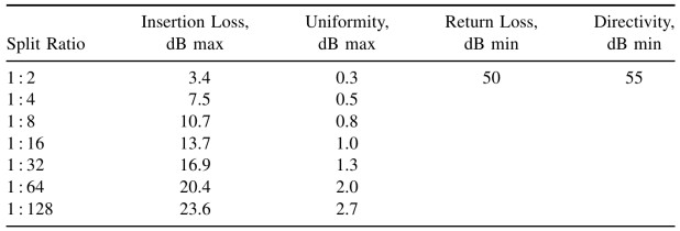
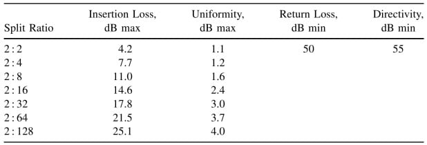
PLC Splitter is used in GPON ODNs where large, concentrated splits are needed (as distinct from trees made of several separately located 1 × 4 splitters, for example). The tables below list typical parameters for 1 × N (single-input) and 2 × N PLC splitters.
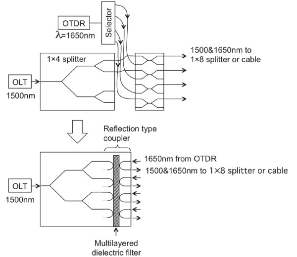
For testing, the optical time-domain reflectomer (OTDR) is used at the wavelength of 1650 nm. The splitter has reflection-type couplers at the splitter outputs, made using multiayered dielectric filters. It is compact but fibers have to be attached to both ends of the input and output ports. There is not much difference in the loss characteristics between the two types of coupler (splitter).
The insertion loss of the commercially available 1×16 Fiber coupler, for example, is about 13 to 14 dB, including excess loss of 1 to 2 dB in both fiber type and PLC coupler/splitter. The polarization dependent loss is as small as 0.3 dB. Consider a passive double star configuration configured with 1× 4 splitter in the central office and 1× 8 splitter in the outside plant. In order to test in-service fiber cables in the ODN, fiber optic couplers have to be inserted between the 1× 8 splitter and the ONUs, and the output at the wavelength of 1650 nm from the OTDR signal has to be cut off in front of the ONU and the OLT to pass only signals at 1310 nm and 1550 nm. Compared with the separate device configuration, the integrated device will provide ease of handling because the input ends of the couplers and the splitter are on opposite sides.
SFP Transceiver CWDM, DWDM, BiDi, SONET, SDH, 100M,1G,4G, Copper SFP |
MTP/MPO Cable.jpg "Fiber-Mart") 12 Fiber, 24FiberMPO/MTP Turnk Cables & Cassettes |
CWDM MUX DEMUX 1-18 Channels Mux & Demux, LGX, ABS, Rack Chassis Types |
-consulting for technical supports or relevant product buying guide
Email to [email protected]


No comments have been posted yet.