

.webp)


Power over Ethernet
THE INTRODUCTION OF POE
Power over Ethernet (PoE) is a technology that enables the safe transfer of Direct Current (DC) electrical power along with data over standard network cabling. Both the data and the power may share the same wire, and each is independent and unaffected by the other. This tutorial provides a comprehensive overview of PoE technology and describes how to use fiber optic cabling to overcome the 100 meters distance limitation of copper network cabling.
THE BENEFITS OF POE
What are the benefits of using PoE and why would a network designer want to use this technology?
PoE is presently deployed where access to Alternating Current (AC) power is inconvenient, expensive or infeasible to supply. PoE can power devices that are located in ceilings, on rooftops, light poles, along fences, pipelines, transit routes and other out-of-the-way locations. The cost of bringing electrical power to each device is eliminated by powering the equipment through the Unshielded Twisted Pair (UTP) cable.
Flexibility: Easily move devices to wherever a LAN cable can go; Install devices where it is difficult to get power. Simplicity: Install only Ethernet cable to the end device; Minimizes cable clutter and saves space. Safety: No AC power is needed for outdoor applications; No need to meet electrical building codes. Cost Savings: No need to install power outlets; No need to hire licensed electricians. Functionality: End devices can be reset remotely.
PoE is also green. The following excerpt is about smart buildings and energy efficiency:
A smart building is where an IP network is able to provide Power-over-Ethernet to a range of "plug load" devices. PoE not only supplies low voltage rather than high voltage power to these devices but more importantly, provides the means to control power to the device. The result can be reduced consumption of power to devices, reduced power usage and a greener building. In addition PoE reduces the use of materials, eliminating the need to provide a power cable to the device.
Most advocates expect PoE to become a global, long-term DC power cabling standard and replace "wall wart" converters, which are difficult to manage, waste energy, are often poorly designed, and are easily vulnerable to damage from surges and brownouts.
COPPER CABLING AND PORTS
PoE utilizes standard network cabling. This network cabling is referred to as Ethernet cable, copper network cable, Category 5 or 6 cable, and UTP cable. This cabling connects to a network device through an RJ-45 Port.
POE DEVICES
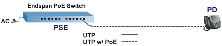
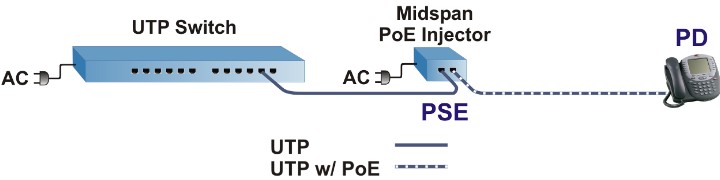
Power Sourcing Equipment (PSE) is the device that provides, or injects, power in a PoE network. There are two types of PSE: endspan and midspan. As the names imply, the endspan is located at the end of a link segment, while a midspan is located in the middle of the link segment.
A Powered Device (PD) is a device that draws power from the PSE. One example of a PD is a desktop Voice over IP (VoIP) phone. There are many examples of PDs provided in this tutorial.
An endspan PoE switch is an Ethernet switch with PoE capabilities built-in, so both data and power are sent over the UTP cable.
A midspan PoE injector is typically a two-port device that injects power at a point along the UTP cabling. Midspans are used to power PDs that are connected to switches that do not provide PoE. The midspan injects DC power to the cable, and the data passes through the injector transparently. With most midspan injectors, the 100 meters distance limit applies to the entire span, from the switch to PD.
Note: A valid PD (per the IEEE standards) presents an electrical signature to the PSE. Before the PSE sends power over the wires, it looks for this electrical signature. If not present, the PSE does NOT apply power to the wires. The PSE will , however, continue to send the data.
The related devices in Fiber-Mart include PoE Media Converter and PoE Switch.
IEEE POE STANDARDS
In 2003 the IEEE ratified the 802.3af PoE standard that allows up to 15.4 Watts of power for each port. Late in 2009, the IEEE ratified the 802.3at PoE Standard known as PoE+. 802.3a t is necessary because PD vendors are starting to produce devices that require more power than the 15.4 Watts available with 802.3af. With 802.3at , PDs can be powered with up to 25.5 Watts. 802.3at is backward compatible with 802.3af . If a PSE is "at" and the PD is "af", it will work fine. The PSE recognizes that the PD is "af" and only gives it as much power as it needs. The reverse situation will not work however, if the PSE is only "af" it will not be able to power an "at" PD. Prior to these standards , several device manufacturers were implementing their own proprietary implementations of PoE. The most common type is legacy Cisco VoIP.
Note: Although the IEEE has specified PoE and PoE+ power levels, there are non-standard devices on the market that provide power levels outside of the IEEE specifications.
The PoE or PoE+ power level supplied by a PSE will vary, depending on the power requirement of the PD. For example, an IEEE 802.3af standard-compliant PSE can supply up to 15.4 watts of power, but if the PD is an IP phone that requires only 6 watts, then the PSE will supply 6 watts of PoE.
IEEE PoE Powering Options over UTP Cabling
PoE supports four powering options using different combinations of the eight pins on a standard RJ-45 port that connect to four pairs of wire in UTP cabling.
IEEE Standard Based: IEEE Alternative A (power on pins 1/2 and 3/6); IEEE Alternative B (power on pins 4/5 and 7/8).
The IEEE PoE standard specifies two modes of detection and powering different pins and wires: Alternative A or Alternative B. Both Alternative A and B support either Fast Ethernet or Gigabit Ethernet, and PoE or PoE+.
To be IEEE standards compliant, a PD must support both A lternative A and Alternative B, whereas a PSE may support either A lternative A or Alternative B, or both.
Legend for the following schematic illustrations:

10/100BASE-T Alternative A: 10/100BASE-T Alternative A injects the positive DC power on pins 1 and 2 and the negative DC power on pins 3 and 6. In Fast Ethernet, these are also the data pairs, so the data and power share the same wires . The "sharing" of the wire is accomplished using a technique called Phantom Power, which was originally used as a method for transmitting DC electrical power through microphone cables to operate microphones that contain active electronic circuitry.
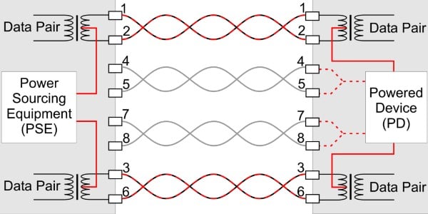
10/100BASE-T Alternative B: 10/100BASE-T Alternative B puts the positive DC power on pins 4 and 5 and the negative DC power on pins 7 and 8. In Fast Ethernet, these are the "spare" pairs, so the electrical current is not sharing wires with data, and there is no Phantom Power.
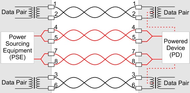
1000BASE-T Alternative A: IEEE 1000BASE-T Alternative A puts the positive DC power on pins 1 and 2 and the negative DC power on pins 3 and 6. In Gigabit Ethernet, all four pairs carry data, so Phantom Power is always required for Gigabit PoE.
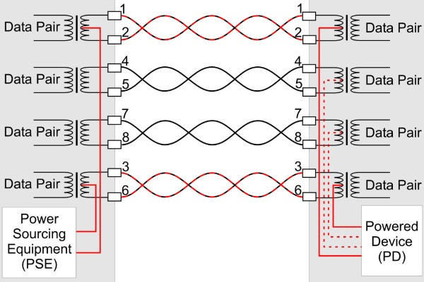
1000BASE-T Alternative B: IEEE Alternative B puts the positive DC power on pins 4 and 5 and the negative DC power on pins 7 and 8.

Non-Standard Based: Legacy non-IEEE is a proprietary detection and powering mode that Cisco implemented before the 802.3af standard was ratified in 2003. This mode uses pins 4/5 and 7/8 for the DC power, but the polarity is reversed.
Legacy "Large-Capacitor Detection" is available for both Alternative A and B powering. For legacy VoIP devices, "Large-Capacitor Detection" is typically Alternative B (power on pins 4/5 and 7/8), but the detection method does not follow the IEEE standards. Instead, the PSE looks at the PD for a unique large capacitance signature. If it sees that signature, then it applies power per Alternative B.
POE AND PoE+ POWERED DEVICES
PoE and PoE+ enable the powering of a wide variety of network devices.
IP Phones: Voice over IP (VoIP) phones are widely adopted and used in businesses worldwide. Since they are network devices, they utilize PoE to draw power and voice data over the network cable. Telepresence Video Phones and Video Consoles: Video Conference Terminals used in telepresence and teleconferencing applications can be powered by PoE, and require high-bandwidth connectivity. IP Cameras: IP Network Cameras are used in security, surveillance and traffic monitoring applications where the cameras are installed in high, hard-to-reach locations. IP cameras are also used for quality assurance in manufacturing (assembly lines, paper and lumber mills, etc.) and food processing. These applications can utilize high-speed, high-resolution cameras that can require Gigabit data rates. Wireless Devices: Wireless technology is growing in applications and deployments. Wireless LAN and WAN access points and WiMAX antennae are typically powered by PoE because they are installed in ceilings and rooftops. RFID netw orks also use PoE powered access points. Access Control Devices and Badge Readers: High security facilities like businesses, hospitals, airports and military facilities utilize door lock and badge-reader systems that require power at each door to control and monitor building access. IP Clocks: PoE IP clocks are powered over the Ethernet cable, so there is no need for batteries or AC power. All clocks are synchronized to one Simple Network Time Protocol (SNTP) server, maintaining accurate and consistent time across all clocks. IP clocks can also save labor costs by automatically resetting after a power outage, and adjusting for daylight savings time. Messaging and Digital Signage Systems: LED signs function as messaging systems that display routine announcements such as bus schedules, local news or weather feeds. LCD Digital signage can display the same types of information, plus advertising, building maps and directions, restaurant menus, etc. During a crisis, the displays function as an Emergency Alert System. Thin Clients: Thin client computer terminals run applications from a server and function as virtual devices. They require less power than traditional PCs and can draw PoE power for both the thin client terminal and the monitor.

802.3at Powered Devices: IEEE 802.3at PoE injects up to 25.5 watts to power a wide variety of high-power PDs, and opens up new possibilities for emerging applications for supplying power to devices connected to the network.
802.11n Wireless Access Points: In September 2009, the IEEE announced the 802.11n wireless standard. Many 802.11n wireless devices require PoE+ power to enable high-bandwidth connectivity over wide areas. PTZ (Pan-Tilt-Zoom) IP Cameras: PTZ IP cameras have additional motors to control the focus and direction of the camera lens and typically require PoE+ power. Weather-Hardened IP Cameras: Cameras used in extremely cold climates feature blowers and de-icers that often require the additional power supplied by PoE+. Laptops: PoE+ laptops will be coming onto the market with lower power requirements and "trickle charging" techniques.
In addition to these Powered Devices, there are retail point-of-sale devices, industrial automation tools, gas detectors, and remote monitoring devices on the market . There is ev en an Ethernet-powered electric guitar.
CHALLENGES DEPLOYING POE
PoE is a useful technology in powering remote devices, but as we see with any copper network cable, the challenge lies in the limited distance and bandwidth of copper UTP cabling. According to the ANSI/TIA/EIA standard for category 5e (CAT5e) cable, (TIA/EIA 568-5-A) the maximum length for a cable segment is 100 meters (328 ft). PSE power injectors, particularly midspans, do not increase the distance of the data network.

INTEGRATING POE AND FIBER
A common solution to overcome the distance and bandwidth limitations of copper is to use fiber optic cabling. Since DC power cannot be conducted over fiber, a media converter that functions as a PSE is used to inject power on the RJ-45 port(s). A media converter with PoE converts the fiber to copper, and sends DC power to the PD over the UTP cabling.
Convert copper to fiber PoE is injected over copper PoE IS NOT injected over Fiber Fiber is run to the AC or DC power source, and PoE is distributed over CAT 5 to the Powered Device.
Longest Distance up to 87 miles Highest bandwidth capacity of Gigabit and more Security Most Reliable
Fiber connectivity to remote devices like 802.11n wireless access points and high-speed cameras that require d ata rates up to one gigabit Campus networks that require fiber connectivity for long-distance, high-bandwidth applications Fiber-to-the-Desk (FTTD) enables high bandwidth voice/data/video for a variety of military and business applications
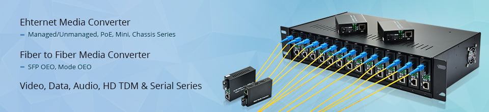
POE MEDIA CONVERTERS
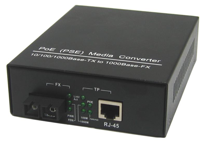
PoE media converters function like other media converters that convert copper to fiber, but they also inject power over the UTP cabling.
PoE media converters are available in Gigabit Ethernet and Fast Ethernet and support PoE (15.4 Watts) or PoE+ (25.5 Watts). PoE media converters function like a PoE mini-switches , and are available in a variety of multi-port configurations, including dual RJ-45 and dual fiber ports. They can support fixed fiber connectors or Small Form Pluggable (SFP) transceivers.
Powering PoE Media Converters
PoE media converters are DC powered, and are available with an AC to DC power supply (100 to 240 VAC) that connects via a barrel connector. They can also be powered with direct DC power input.
How PoE Media Converters Work
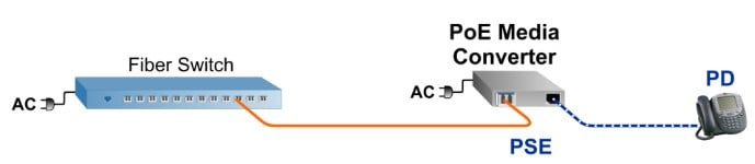
Starting on the left side of the illustration, the fiber originates at a fiber switch. This could be in an IT center, server room, data closet, etc. This can also be a copper switch with a rack of media converters.

The fiber is brought to the PoE media converter located near a convenient AC or DC power source. Not only does the media converter convert the fiber to copper, but it also functions as a PSE and injects PoE power (DC power) over the copper Ethernet cable.
At the other end of the Ethernet cable are the PDs. These PDs can be IP cameras, wireless access points, IP phones, etc. The PDs are in locations up to 100 meters away from the PoE media converter.
Network Architecture Options with PoE Media Converters
Multi-port PoE media converters provide flexible network designs. Single fiber ports are deployed in star topologies with a point-to-point style layout with the fiber switch in the center of the network.

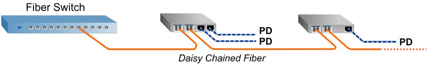
PoE media converters with dual fiber ports enable linking multiple media converters in a linear daisy chain configuration. This architecture can be used in a variety of outdoor applications where PDs such as IP cameras and/or wireless access points are installed along railroad and subway lines, highways, pipelines, mine shafts, perimeter fences, etc.
Dual fiber ports also link multiple media converters in a ring architecture. The fiber switch shown in this diagram supports spanning tree to enable a redundant ring architecture. In the event of a fiber failure in the ring, the fiber switch would reroute the traffic in the opposite direction.

Dual fiber ports can be used to deploy redundant fiber links for mission-critical applications requiring fiber facility protection. There is an active fiber port, and a protection fiber port, that can support a fiber failure switchover of less than 50 milliseconds.

POE MEDIA CONVERTER APPLICATIONS
FTTD: IP Phones, Video Terminals, Thin Clients and PCs
In this application, an FTTD network is deployed to leverage the security, bandwidth and distance benefits of fiber optic cabling. The network originates from a fiber switch in the data closet. This can be the network core in a physically secure area in the building. Fiber optic cables run to each office/desk, where they are terminated by PoE media converters that are powered by an AC or DC power source. The PoE media converters provide fiber to copper media conversion, and they send data and power to desktop items such as IP phones and video conferencing equipment.
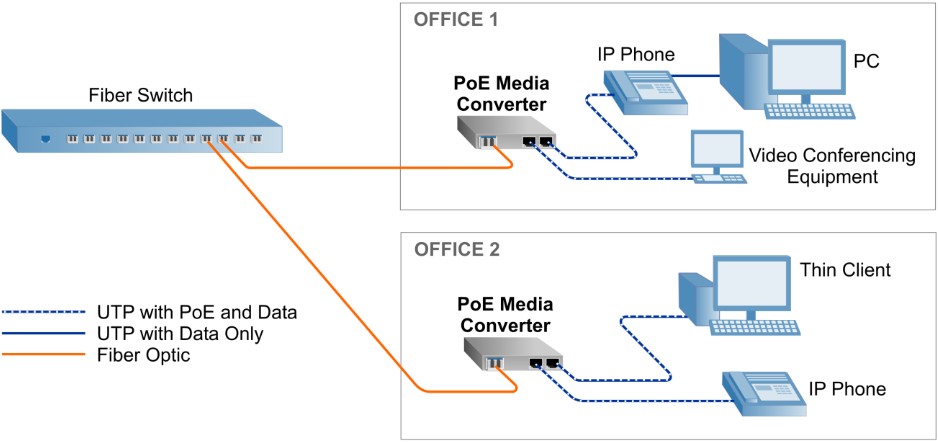
In OFFICE 1, a PoE media converter with two copper ports is used to deliver power and data to an IP phone and a video conferencing terminal. The PC is connected to an auxiliary Ethernet port on the phone, and will receive data but no power. Non-PoE network devices can also be safely connected directly to the media converters. For example, the PC could be connected directly to the PoE media converter (not shown). The PoE media converter can automatically detect that the PC is not a PD, so it will send data, but not power. In OFFICE 2, a PoE media converter with two copper ports is used t o deliver power and data to an IP phone and a Thin Client. PoE can power both the Thin Client terminal and the display.
Building Automation: Access Controls, Clocks and Messaging Systems
Building Automation encompasses all the PoE applications in this tutorial, and PoE is becoming an integral part of building networks and low-voltage systems. In addition, PoE networks reduce energy consumption and can earn points in LEEDs certification.
In this application, IP clocks, badge-reader access devices, messaging signage and HVAC controls are deployed. The environment may be a school campus, office building, hospital, airport, military base, etc. Fiber is used because the required link distances across the building/campus often exceed the 100 meter limitation of UTP cabling.
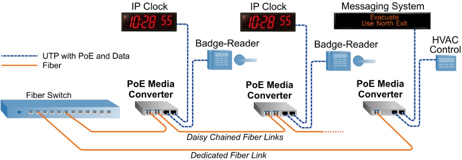
The fiber is distributed from a switch in the network core or main data closet. Daisy chained fiber links connect different rooms/offices, where PoE media converters are located near convenient AC or DC power sources. The PoE media converters have fiber uplink ports and downlink ports, and dual RJ-45 ports that provide data and power to the IP clocks and badge-reader access systems. A dedicated, point-to-point fiber link runs to another location where a PoE media converter provides data and power to an LED messaging sign and an HVAC thermostat control.
Fiber to Wireless Devices
In this application, wireless access points are installed in remote locations in an office building, airport or mass transit system. PoE+ and Gigabit Ethernet is used for 802.11n access points deployed in a daisy chain topology. The number of access points on the daisy chain is limited by the aggregate bandwidth of all the devices.

A dedicated, point-to-point fiber link runs to another location where a PoE + media converter provides data and power to a parabolic WiMAX dish antenna.
Fiber to IP Network Cameras
In this application, IP cameras are installed throughout a facility. The cameras are mounted in remote locations far from the fiber switch video server, and where AC power is not readily available. The fiber is distributed from a switch in the network core or main data closet. Daisy chained fiber links connect to remote locations where PoE media converters are installed near AC or DC power sources. The PoE media converters have fiber uplink ports and downlink ports, and dual RJ-45 ports for two IP cameras at each location.
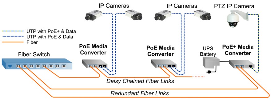
Redundant fiber links are used for a mission-critical security camera. The PoE + media converter has one fiber port for the active fiber link, and one port for the protect fiber link, with fiber failure switchover of less than 50 milliseconds. The PoE+ media converter supplies power to a PTZ camera, and has power protection from an Uninterruptible Power Supply (UPS) Battery back-up.
CONCLUSION
PoE media converters combine the benefits of PoE or PoE+ and fiber optic cabling in a compact, reliable and cost-effective device. Classified as PSE, the PoE media converters provide power to PDs using the same UTP cables that carry the Ethernet data. This enables powering devices in hard-to-reach locations where there is limited access to AC power outlets, or locations where AC power creates safety issues.
Key Features to Consider When Selecting a PoE Media Converter:
PoE+ to future proof applications Out-of-the-box support for IEEE Alternative A and B, and Legacy Power detection options (without the need for jumper wires or external cables) Jumbo Ethernet Frames to enhance throughput for reliable data flow Multiple port configurations for deploying a variety of architectures and topologies:
Daisy chain media converters or install in ring topologyRedundant fiber with less than 50ms switch over timeDual UTP ports for powering two PoE devices per converter Ability to be powered by either AC or DC power source Industrial hardened temperature ranges for outdoor applications Determines and delivers the specific power level required by the PD Fully configurable DIP-switches for easy set up:
Link Fault Propagation ModesPoE Power Reset on fiber Rx loss that automatically resets the remote PD
Fiber-Mart's PoE Media Converter Solution
Fiber-Mart's PoE Media Converters support the IEEE 802.3af (PoE ) or 802.3at (PoE+) standards, and are the first PoE media converters on the market to support the high-power PoE+ standard. Models are available in Gigabit 1000BASE-X fiber to 10/100/1000 UTP and Fast Ethernet 100BASE-FX fiber to 10/100 UTP. A variety of port configurations are available, including single or dual SFP and single or dual powered UTP ports. Models with dual SFP ports support critical applications that require redundancy and sub 50ms switch over in the event of a fiber failure. The product is DC powered and available with an optional external 100-240VAC universal power adapter.
SFP Transceiver CWDM, DWDM, BiDi, SONET, SDH, 100M,1G,4G, Copper SFP |
MTP/MPO Cable.jpg "Fiber-Mart") 12 Fiber, 24Fiber MPO/MTP Trunk Cables & Cassettes |
CWDM MUX DEMUX 1-18 Channels Mux & Demux, LGX, ABS, Rack Chassis Types |
-consulting for technical supports or relevant product buying guide
Email for [email protected]


No comments have been posted yet.